DESCRIPTION AND OPERATION
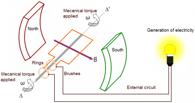
As a conductor cuts across the lines of force in a magnetic field, it generates a current. This method of inducing a current is called induction. There are three rules for induction:
When a conductor cuts through lines of force, it induces an electromotive force (EMF), or voltage.
Either the magnetic field or the conductor needs to be moving for this to happen.
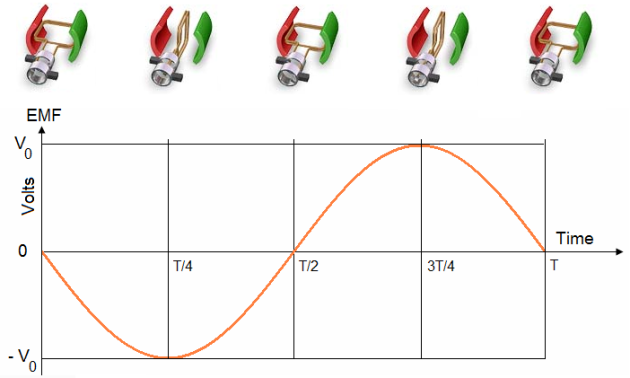
If the direction of the cutting across the magnetic field changes, the direction of the induced EMF also changes.
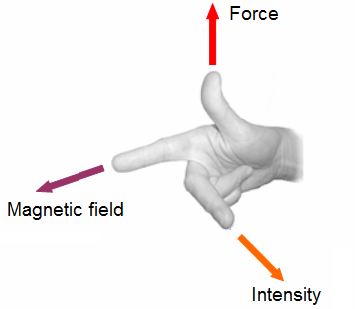
To find the direction of motion of a conductor, extend the thumb, forefinger, and middle finger of your right hand so they are at right angles to each other.
If the forefinger is pointed in the direction of magnetic flux (north to south) and the middle finger is pointed in the direction of current flow in the conductor, the thumb will point in the direction the conductor will move.
1. FARADAY'S LAW:
Accordingly, Faraday's law states that induced voltage can be determined by the number of turns in a coil, and how fast the coil cuts through a magnetic field. Therefore, the more turns in a coil or the stronger the magnetic field, the more voltage induced.
In addition, current changes direction depending on which way it cuts across a magnetic field. As depicted in Figure, a coil cutting through a basic magnetic field in a clockwise direction will at first result in a current with positive polarity, but as it cuts across the same field in the opposite direction during the second half of its turn, the polarity becomes negative.
If S is the area of the loop, N the number f loops, B the induction field, the induction flux across the loop is:
![]() so
so ![]()
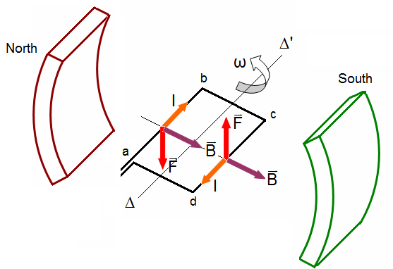
The force applied in the two segments perpendicular to the magnetic fields is equal to F = ilB: where “i” is the intensity and l the distance between the two segments.
Hence, the mechanical torque acting the loop is ![]() ,where S is the area of the loop.
,where S is the area of the loop.
Faraday's law:
A current-carrying conductor placed in a magnetic field, perpendicular to the lines of flux, tends to move in a direction perpendicular to the magnetic lines of flux.
There is a definite relationship between the direction of the magnetic field, the direction of current in the conductor, and the direction in which the conductor tends to move.
This relationship is best explained by using the right-hand rule.
2. GENERATORS AND MOTORS:
Generators:
Input: torque,
Outpout: electricity.

Motors:
Input: electricity,
Outpout: torque.

3. AC GENERATOR:
Fundamentally, electric generators operate on the same principle, regardless of whether they produce AC or DC. Internally, all generators produce AC. The generator's operation is based on Faraday's law of EM induction.
In brief, if a coil (or winding) is linked to a varying magnetic field, then an electromotive force (EMF), or voltage is induced across the coil.
4. OPERATION AND CONSTRUCTION OF REVOLVING ARMATURE AND REVOLVING FIELD TYPE AC GENERATORS:
4.1. Revolving-armature alternators:
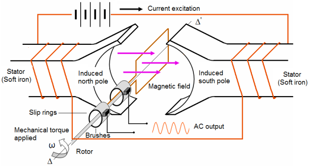
In the rotating-armature alternator the armature rotates in a stationary magnetic field as shown in figure. In the alternator, the generated AC is brought to the load unchanged by means of slip rings.
The rotating armature is found only in alternators of low power rating and generally is not used to supply electric power in large quantities.
4.2 Revolving-field alternators:
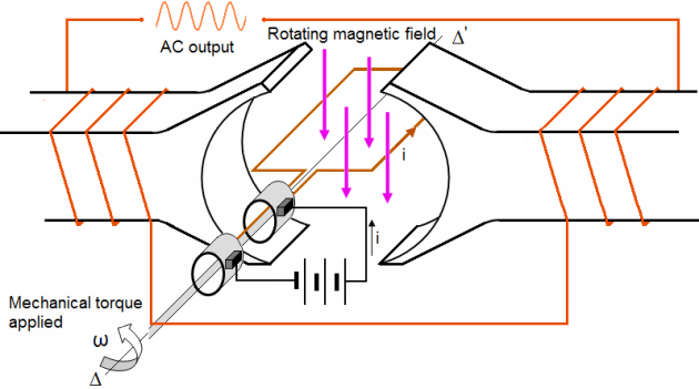
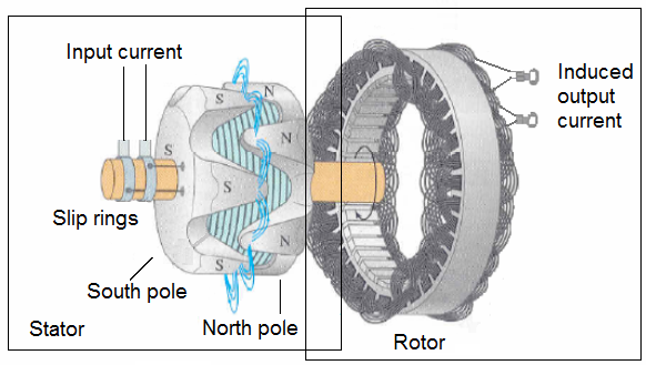
The rotating-field alternator has a stationary armature winding and a rotating-field winding as shown in figure below.
The advantage of having a stationary armature winding is that the generated voltage can be connected directly to the load. A rotating armature requires slip rings and brushes to conduct the current from the armature to the load.
The armature, brushes, and slip rings are difficult to insulate, and arc-overs and short circuits can result at high voltages. For this reason, high-voltage alternators are usually of the rotating-field type. The stationary armature, or stator, of this type of alternator holds the windings that are cut by the rotating magnetic field. The voltage generated in the armature as a result of this cutting action is the AC power that will be applied to the load.
The stators of all rotating-field alternators are about the same. The stator consists of a laminated iron core with the armature windings embedded in this core. The core is secured to the stator frame.
4.3. Alternator rotors:
There are two types of rotors used in rotating-field alternators, the turbine-driven rotor and the salient-pole rotor.
Turbine-driven rotor:
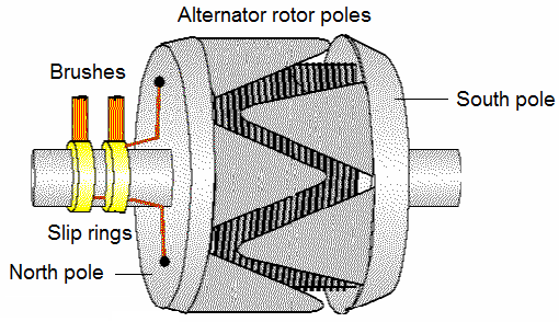
The windings in the turbine-driven rotor are arranged to form two or four distinct poles. The windings are firmly embedded in slots to withstand the tremendous centrifugal forces encountered at high speeds.
Salient-pole rotor:
The salient-pole rotor is used in low-speed alternators.
Salient-4-poles generator :
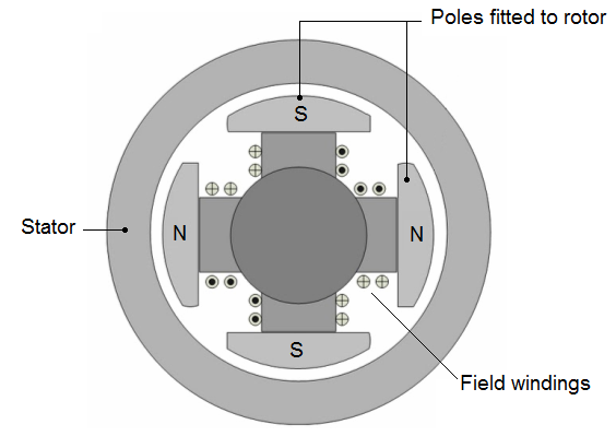
The salient-pole rotor often consists of several separately wound pole pieces, bolted to the frame of the rotor.
If you could compare the physical size of the two types of rotors with the same electrical characteristics, you would see that the salient-pole rotor would have a greater diameter.
At the same number of revolutions per minute, it has a greater centrifugal force than does the turbine-driven rotor. To reduce this force to a safe level so that the windings will not be thrown out of the machine, the salient pole is used only in low-speed designs.
4.4. Alternator characteristics and limitations:
Alternators are rated according to the voltage they are designed to produce and the maximum current they are capable of providing.
The maximum current that can be supplied by an alternator depends upon the maximum heating loss that can be sustained in the armature. This heating loss (which is an RI2 power loss) acts to heat the conductors, and if excessive, destroys the insulation.
Thus, alternators are rated in terms of this current and in terms of the voltage output: the alternator rating in small units is in volt- amperes; in large units it is kilovolt-amperes. When an alternator leaves the factory, it is already destined to do a very specific job.
The speed at which it is designed to rotate, the voltage it will produce, the current limits, and other operating characteristics are built in. This information is usually stamped on a nameplate on the case so that the user will know the limitations.
5. SINGLE PHASE, TWO PHASES AND THREE PHASE ALTERNATORS:
5.1. Single phase:
A generator that produces a single, continuously alternating voltage is known as a SINGLE-PHASE alternator. All of the alternators that have been discussed so far fit this definition. The stator (armature) windings are connected in series. The individual voltages, therefore, add to produce a single-phase AC voltage.
Single-phase alternators are found in many applications. They are most often used when the loads being driven are relatively light. The reason for this will be more apparent as we get into multiphase alternators (also called polyphase).
Power that is used in homes, shops, and ships to operate portable tools and small appliances is single-phase power. Single-phase power alternators always generate single-phase power. However, all single-phase power does not come from single-phase alternators. This will sound more reasonable to you as we get into the next subjects.

5.2. Two-phase alternators:
Two phase implies two voltages if we apply our new definition of phase. And, it's that simple. A two-phase alternator is designed to produce two completely separate voltages.
Each voltage, by itself, may be considered as a single-phase voltage.
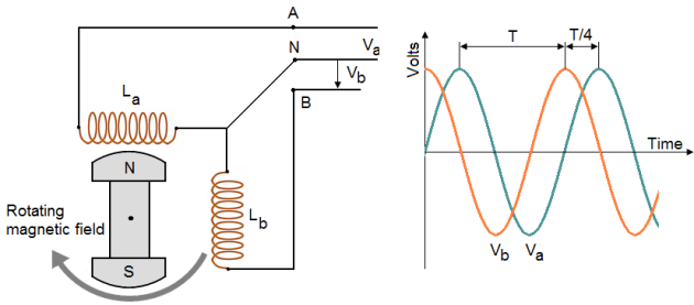
Figure shows a simplified two-pole, two-phase alternator.
Note that the windings of the two phases are physically at right angles (90º) to each other. You would expect the outputs of each phase to be 90º apart, which they are.
The graph shows the two phases to be 90º apart, with phase 1 and phase 2.
Now, let's go back and see the similarities and differences between our original (single-phase) alternators and this new one (two-phase). Note that the principles applied are not new. This alternator works the same as the others we have discussed.
The stator in figure consists of two single-phase windings completely separated from each other. Each winding is made up of two windings that are connected in series so that their voltages add. The rotor is identical to that used in the single-phase alternator. In the left-hand schematic, the rotor poles are opposite all the windings of phase 1.
Therefore, the voltage induced in phase 1 is maximum, and the voltage induced in phase 2 is zero. As the rotor continues rotating clockwise, it moves away from the b windings and approaches the a windings. As a result, the voltage induced in phase b decreases from its maximum value, and the voltage induced in phase a increases from zero.
In the right-hand schematic, the rotor poles are opposite the windings of phase b.
Now the voltage induced in phase b is maximum, whereas the voltage induced in phase a has dropped to zero.
Notice that a 90-degree rotation of the rotor corresponds to one-quarter of a cycle, or 90 electrical degrees. The waveform picture shows the voltages induced in phase 1 and 2 for one cycle.
The obvious advantage, so far, is that we have two separate output voltages. There is some saving in having one set of bearings, one rotor, one housing, and so on, to do the work of two.
There is the disadvantage of having twice as many stator coils, which require a larger and more complex stator.
5.3 Three-phase alternator :
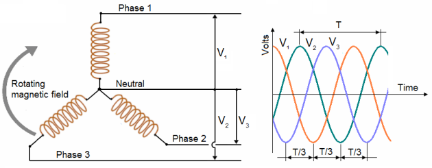
A three phase, or polyphase circuit, is used in most aircraft alternators, instead of a single or two phase alternator. The three phase alternator has three single phase windings spaced so that the voltage induced in each winding is 120° out of phase with the voltages in the other two windings.
A schematic diagram of a three phase stator showing all the coils becomes complex and difficult to see what is actually happening.
A simplified schematic diagram, showing each of three phases, is illustrated in figure below.
The rotor is omitted for simplicity (here is showing by a grey arrow).
The waveforms of voltage are shown to the right of the schematic.
The three voltages are 120° apart and are similar to the voltages which would be generated by three single phase alternators whose voltages are out of phase by angles of 120°.
The three phases are independent of each other.
Rather than have six leads from the three phase alternator, one of the leads from each phase may be connected to form a common junction. The stator is then called wye or star connected.
The common lead may or may not be brought out of the alternator. If it is brought out, it is called the neutral lead. The simplified schematic shows a wye connected stator with the common lead not brought out. Each load is connected across two phases in series.
Thus, (common, 1, 2) is connected across phases 1 and 2 in series; (common, 1, 3) is connected across phases 1 and 3 in series; and (common, 2, 3) is connected across phases 2 and 3 in series.
Therefore, the voltage across each load is larger than the voltage across a single phase.
The total voltage, or line voltage, across any two phases is the vector sum of the individual phase voltages.
6. THREE PHASE WYE & DELTA CONNECTIONS ADVANTAGE AND USE:
6.1. Wye-three-phase alternator:
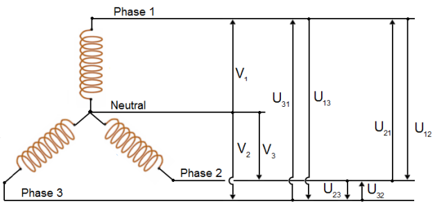
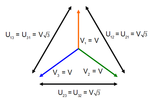
Rather than having six leads coming out of the three-phase alternator, the same leads from each phase may be connected together to form a wye (Y) connection, as shown in figure . It is called a wye connection because, without the neutral, the windings appear as the letter Y (sometimes is also called Star), in this case sideways or upside down.
The neutral connection is brought out to a terminal when a single-phase load must be supplied.
Phase voltage:
Single-phase voltage is available from neutral to phase 1, neutral to phase 2, and neutral to phase 3. Single voltage is equal at V.
Line voltage:
In a three-phase, Y-connected alternator, the total voltage, or line voltage, across any two of the three line leads is the vector sum of the individual phase voltages.
Each line voltage U is ![]() times one of the phase voltages.
times one of the phase voltages.
Because the windings form only one path for current flow between phases, the line and phase currents are the same (equal).
6.2. Delta-three-phase alternator:
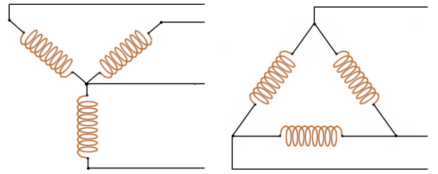
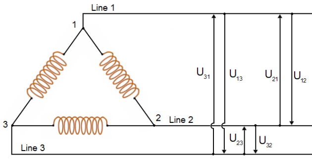
A three-phase stator can also be connected so that the phases are connected end-to-end; it is now delta connected (Delta because it looks like the Greek letter delta Δ)
In the delta connection, line voltages are equal to phase voltages, but each line current is equal to ![]() times the phase current.
times the phase current.
Both the wye and the delta connections are used in alternators. The majority of all alternators in use in the aircraft today are three-phase machines. They are much more efficient than either two-phase or single-phase alternators.
With these connections only three wires come out of the alternator. This allows convenient connection to three-phase motors or power distribution transformers.
It is necessary to use three-phase transformers or their electrical equivalent with this type of system.
6.3. Three-phase transformer:
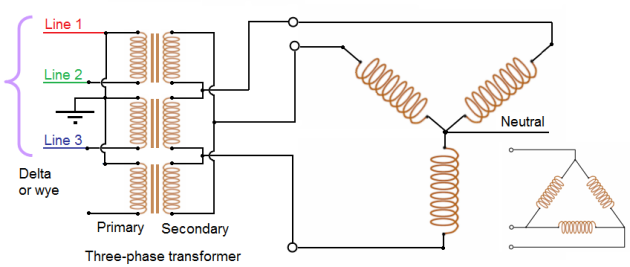
A three-phase transformer may be made up of three, single-phase transformers connected in delta, wye, or a combination of both. If both the primary and secondary are connected in wye, the transformer is called a wye-wye. If both windings are connected in delta, the transformer is called a delta-delta.
Figure shows single-phase transformers connected delta or wye for operation in a three-phase system. You will note that the transformer windings are not angled to illustrate the typical delta as has been done with alternator windings. Physically, each transformer in the diagram stands alone. There is no angular relationship between the windings of the individual transformers.
However, if you follow the connections, you will see that they form an electrical delta. The primary windings, for example, are connected to each other to form a closed loop. Each of these junctions is fed with a phase voltage from a three phase alternator.
The alternator may be connected either delta or wye depending on load and voltage requirements, and the design of the system.
With a delta-delta configuration, the load may be a three-phase device connected to all phases; or, it may be a single-phase device connected to only one phase. At this point, it is important to remember that such a distribution system includes everything between the alternator and the load.
Because of the many choices that three-phase systems provide, care must be taken to ensure that any change of connections does not provide the load with the wrong voltage or the wrong phase.
One distinct advantage of a Delta-connected system is its lack of a neutral wire.
With a Y-connected system, a neutral wire was needed in case one of the phase loads were to fail open (or be turned off), in order to keep the phase voltages at the load from changing. This is not necessary (or even possible!) in a Delta-connected circuit. With each load phase element directly connected across a respective source phase winding, the phase voltage will be constant regardless of open failures in the load elements.
