DESCRIPTION AND OPERATION
If DC is required, a device to rectify, or change, the AC to DC is needed. The DC generators use a device called a commutator just for such a purpose.
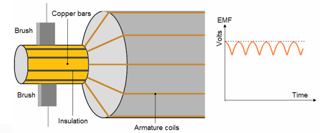
Replace the brushes with slip rings and you get a DC generator. Notice the voltage is not steady. The coil is shown at the top and bottom of the shaft.
A DC generator consists of a number of conducting coils and a magnetic field. The coils are called the armature. Relative motion between the coils and magnetic field induces voltage in the coils. This action is called EMF. The required DC is provided by an external source called an exciter.
1. COMMUTATION:
1.1. Two-coil DC generator:
Commutation is the process by which a DC voltage output is taken from an armature that has an AC voltage induced in it. The commutation mechanically reverses the armature loop connections to the external circuit. This occurs at the same instant that the voltage polarity in the armature loop reverses.
In figure commutation occurs simultaneously in the two coils that are briefly short-circuited by the brushes.
A DC voltage is applied to the load because the output connections are reversed as each commutator segment passes under a brush. The segments are insulated from each other.
The brushes are positioned on the commutator so that each coil is short-circuited as it moves through its own electrical neutral plane.
As you have seen previously, there is no voltage generated in the coil at that time. Therefore, no sparking can occur between the commutator and the brush. Sparking between the brushes and the commutator is an indication of improper commutation. Improper brush placement is the main cause of improper commutation.
1.2. Multi-coil DC generator:
If we increase the number of turns and arrange them as shown in figure below, we can smooth out the variations in voltage.
2. DC POWER GENERATOR CONSTRUCTION:
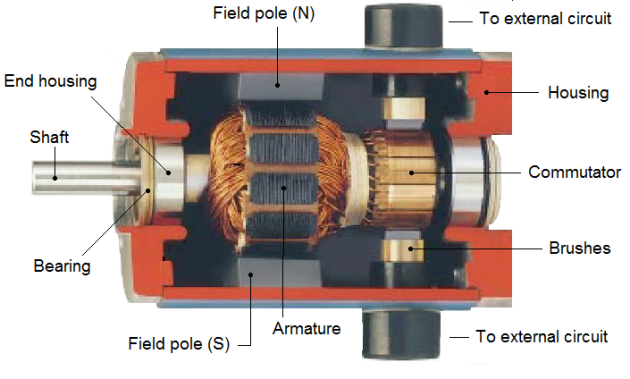
The various parts of a DC generator are listed below, together with its function:
Main frame:
It is sometimes called the yoke or housing. It functions to support all other components and to complete the magnetic path between the field poles.
Field poles:
They are made of many thin lamination of iron, joined together and bolted to the inside of the frame. Its function is to support the field winding, and to concentrate the magnetic flux produced.
Field windings:
They are copper wire coils mounted on the pole pieces such that when they are energized, a magnetic field will be set up between the poles. The electrical connections of the field windings determine the type of DC generator.
End housing:
These are supports or the two ends of the main frame, which contains bearings for the armature. The front housing will also support the brush assembly.
Brush holder:
Secured to the front end housing by clamps, it also supports to the brushes and their connecting wires.
Armature assembly:
It is the rotating element within the generator. It is made up of a shaft, an armature windings and a commutator.
The armature core is laminated and slots are cut to receive the armature windings.
The armature windings are connected to the commutator segments, whereby the generated EMF in the armature windings are being taped out to the external circuit by means of brushes.
Brushes:
They write on commutator and carry the generated EMF to the load. They are made of carbon and are housed in the brush holders. A flexible braided conductor, called a pigtail, connects each brush to the external circuit.
3. TYPES OF DC GENERATORS:
3.1. Series-wound generator:
In the series-wound generator, shown in figure, the field windings are connected in series with the armature. Current that flows in the armature flows through the external circuit and through the field windings.
The external circuit connected to the generator is called the load circuit.
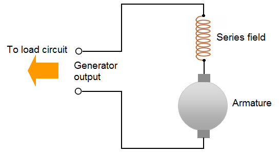
A series-wound generator uses very low resistance field coils, which consist of a few turns of large diameter wire.
The voltage output increases as the load circuit starts drawing more current. Under low-load current conditions, the current that flows in the load and through the generator is small. Since small current means that a small magnetic field is set up by the field poles, only a small voltage is induced in the armature.
If the resistance of the load decreases, the load current increases. Under this condition, more current flows through the field. This increases the magnetic field and increases the output voltage.
A series-wound DC generator has the characteristic that the output voltage varies with load current. This is undesirable in most applications. For this reason, this type of generator is rarely used in everyday practice.
3.2. Shunt-wound generator:
In this field winding is connected in parallel with the armature conductors and have the full voltage of the generator applied across them. The field coils consist of many turns of small wire. They are connected in parallel with the load. In other words, they are connected across the output voltage of the armature.
Current in the field windings of a shunt-wound generator is independent of the load current (currents in parallel branches are independent of each other). Since field current, and therefore field strength, is not affected by load current, the output voltage remains more nearly constant than does the output voltage of the series-wound generator.
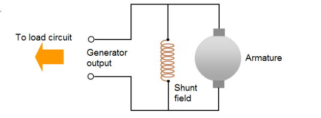
In actual use, the output voltage in a DC shunt-wound generator varies inversely as load current varies. The output voltage decreases as load current increases because the voltage drop across the armature resistance increases (E = RI).
In a series-wound generator, output voltage varies directly with load current. In the shunt-wound generator, output voltage varies inversely with load current. A combination of the two types can overcome the disadvantages of both. This combination of windings is called the compound-wound DC generator.
3.3. Compound-wound generator:
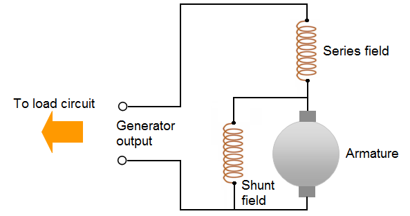
Compound-wound generators have a series-field winding in addition to a shunt-field winding, as shown in figure. The shunt and series windings are wound on the same pole pieces. They can be either short-shunt or long-shunt as shown in figures.
In a compound generator, the shunt field is stronger than the series field.
When series field aids the shunt field, generator is said to be commutatively-compounded. On the other hand if series field opposes the shunt field, the generator is said to be differentially compounded.
In the compound-wound generator when load current increases, the armature voltage decreases just as in the shunt-wound generator.
Compound-wound long shunt generator :
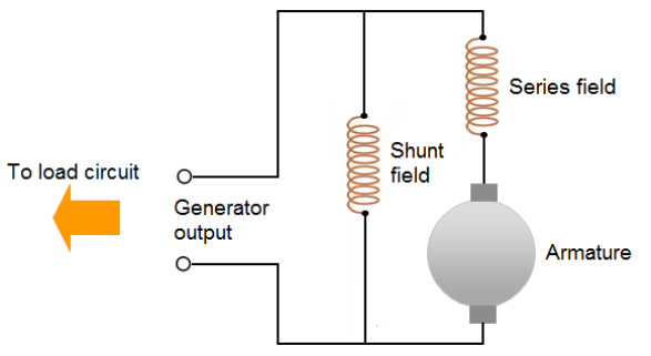
This causes the voltage applied to the shunt-field winding to decrease, which results in a decrease in the magnetic field. This same increase in load current, since it flows through the series winding, causes an increase in the magnetic field produced by that winding.
Compound-wound short shunt generator :
5. ALTERNATORS RECTIFIERS:
The alternator rectifier has a number of advantages over the generator. In the first place, one of the most important advantages of the alternator is the fact that load current is generated in the stator or stationary winding and does not have to flow through brushes to the load.
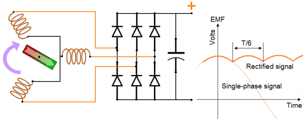
The coils in this stator are connected as three windings, joined together to form a Y.
There are seven pairs of poles in the rotor and seven coils in each leg of the Y, so, as the rotor turns within the stator, three phases of alternating current are generated.
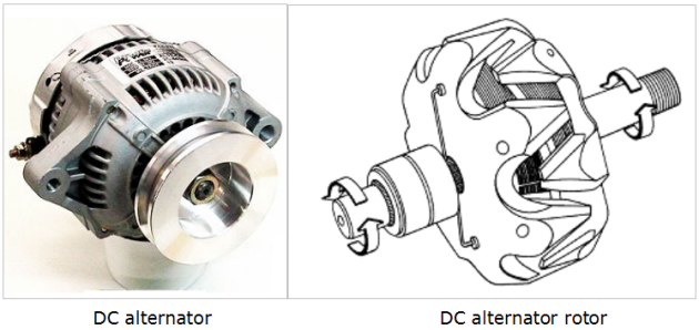
The rotor of an aircraft alternator is made up of two soft iron end pieces with intermeshing poles pressed onto the shaft, on either side of a drum-type exciter coil. The ends of the coil are attached to two slip rings, and the entire rotor is supported in the housing with either ball or needle bearings.
The magnetic field produces alternating north and south poles in the soft iron, interlacing fingers formed by the two end-pieces
The rectifier of an alternator is made up of six silicon diodes, three mounted in the end frame, and the other three pressed into an insulated heat sink. Figure is a schematic of an aircraft alternator showing the three-phase Y-connected stator, the single-phase rotor, and the six rectifier diodes.
A capacitor is often placed at the output of the rectifier to protect the diodes from voltage surges caused by their blocking the current.

