DESCRIPTION AND OPERATION
1. CONTROL OF DC GENERATORS:
1.1. Types of controls:
Voltage control:
An aircraft DC generator is self-excited; that means that the current used to produce electromagnetism in the field comes from the armature. If there were no control in the field circuit the generator would run away with itself and burn out its windings. As the generator starts to turn, a voltage begins to build up because of residual magnetism in the field frame.
This voltage causes current to flow in the field coils and increases the voltage. As voltage rises, field current increases and, by a bootstrapping action, the voltage will continue to rise as indicated by the dashed curve in Figure below.
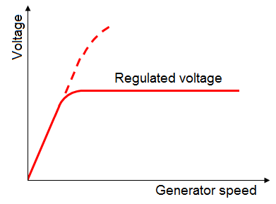
When the voltage required by the system is reached, the voltage regulator, which is actually a variable resistor in the field circuit, will automatically decrease the field current and prevent the voltage rising above the regulated level. The voltage is held relatively constant by controlling the amount of field current allowed to flow.
Current limitation:
All generators are rated with regard to the amount of current they are allowed to produce. Large, high-output generators are prevented from exceeding their rated current output by a special heavy-duty fuse called a current limiter between the generator output and the main bus.
Generator systems having lower outputs, such as are found on many smaller general aviation aircraft, have an automatic current limiter which places a variable resistance in the field circuit any time the output current exceeds the generator rating.
This resistor decreases field current and lowers output voltage, which in turn decreases the output current.
Both the voltage regulator and the current limiter place a resistance in the generator field-the voltage regulator, when output voltage exceeds the set limit, and the current limiter, when output current becomes excessive.
Reverse-current prevention:
An aircraft DC generator is placed in the circuit so it will provide current for the load and charge the battery when the output voltage is higher than that of the battery. When the engine is idling or when it is not operating, the battery could discharge through the armature windings if some provision were not made to prevent this reverse flow of electricity.
Almost all generators use a voltage-operated switch in the generator output that keeps the generator off of the aircraft bus any time its voltage is below that of the battery.
When the generator voltage builds up above that of the battery, the switch closes, placing the generator in service.
When the generator output drops below that of the battery, current flows from the battery into the generator, and this reverse flow neutralizes the magnetic effect which had closed the switch. The contacts open and take the generator off the line.
Alternators are attaining a great deal of popularity as a source of direct current and, as we will see, instead of rectifying their AC output with a commutator and brush arrangement as the generator does, solid-state diodes do the rectifying.
These diodes not only change the generated AC into DC, but they prevent any flow of direct current from the battery entering the alternator stator windings.
Paralleling requirements:
When two generators feed the electrical system of an airplane, provision must be made to keep the voltage output of the two as near the same as possible, to prevent one generator carrying all of the load while the other carries none.
Carbon-pile voltage regulators, as we will see, have provisions for a load imbalance to automatically increase the voltage of the low generator and at the same time decrease the voltage of the one carrying the greater load.
Vibrator and transistor regulators normally depend on their ability to keep the voltages constant once they have been adjusted.
The generators and regulators are brought up to operating speed and temperature, with their output voltages adjusted, using a highly accurate voltmeter. Then, with both generators on the line and an appreciable load applied, the regulators are adjusted until the generators produce the same current. This procedure, as with any adjustment, must be done in careful accordance with the manufacturer's recommendations.
1.2. Vibrator-type generator control system:
The majority of low-output aircraft generators are regulated with vibrator-type controls. The most familiar regulator has three units in one waterproof, metal-covered housing.
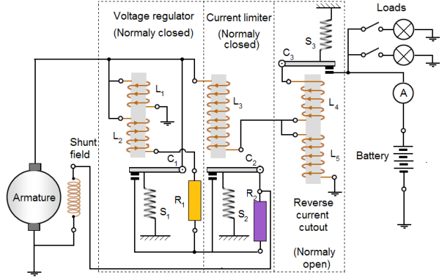
Many aircraft employ a three unit regulator for their generator systems. This type of regulator includes a current limiter and a reverse current cutout in addition to a voltage regulator.
The first action of the three-unit is the voltage control.
The second of the three units is a current regulator to limit the output current of the generator.
The third unit is a reverse current cutout that disconnects the battery from the generator.
If the battery is not disconnected, it will discharge through the generator armature when the generator voltage falls below that of the battery, thus driving the generator as a motor. This action is called “motoring" the generator and, unless it is prevented, it will discharge the battery in a short time.
Voltage control:
The action of vibrating contact C1 in the voltage regulator unit causes an intermittent short circuit between points R1 and L2. When the generator is not operating, spring S1 holds C1 closed; C2 is also closed by S2. The shunt field is connected directly across the armature.
When the generator is started, its terminal voltage will rise as the generator comes up to speed, and the armature will supply the field with current through closed contacts C2 and C1.
As the terminal voltage rises, the current flow through L1 increases and the iron core becomes more strongly magnetized. At a certain speed and voltage, when the magnetic attraction on the movable arm becomes strong enough to overcome the tension of spring S1, contact points C1 are separated.
The field current now flows through R1 and L2. Because resistance is added to the field circuit, the field is momentarily weakened and the rise in terminal voltage is checked. Also, since the L2 winding is opposed to the L1 winding, the magnetic pull of L1 against S1 is partially neutralized, and spring S1 closes contact C1.
Three-unit-regulator for variable speed generators :
Therefore, R1 and L2 are again shorted out of the circuit, and the field current again increases; the output voltage increases, and C1 is opened because of the action of L1. The cycle is rapid and occurs many times per second. The terminal voltage of the generator varies slightly, but rapidly, above and below an average value determined by the tension of spring S1, which may be adjusted.
Current limiter:
The purpose of the vibrator-type current limiter is to limit the output current of the generator automatically to its maximum rated value in order to protect the generator.
As shown in Figure, L3 is in series with the main line and load. Thus, the amount of current flowing in the line determines when C2 will be opened and R2 placed in series with the generator field.
By contrast, the voltage regulator is actuated by line voltage, whereas the current limiter is actuated by line current. Spring S2 holds contact C2 closed until the current through the main line and L3 exceeds a certain value, as determined by the tension of spring S2, and causes C2 to be opened.
The increase in current is due to an increase in load. This action inserts R2 into the field circuit of the generator and decreases the field current and the generated voltage.
When the generated voltage is decreased, the generator current is reduced. The core of L3 is partly demagnetized and the spring closes the contact points. This causes the generator voltage and current to rise until the current reaches a value sufficient to start the cycle again.
A certain minimum value of load current is necessary to cause the current limiter to vibrate.
Reverse-current prevention:
The purpose of the reverse current cutout relay is to automatically disconnect the battery from the generator when the generator voltage is less than the battery voltage. If this device were not used in the generator circuit, the battery would discharge through the generator.
This would tend to make the generator operate as a motor, but because the generator is coupled to the engine, it could not rotate such a heavy load. Under this condition, the generator windings may be severely damaged by excessive current.
There are two windings, L4 and L5, on the soft iron core. The current winding, L4, consisting of a few turns of heavy wire, is in series with the line and carries the entire line current.
The voltage winding, L5, consisting of a large number of turns of fine wire, is shunted across the generator terminals.
When the generator is not operating, the contacts, C3 are held open by the spring S3. As the generator voltage builds up, L5 magnetizes the iron core. When the current (as a result of the generated voltage) produces sufficient magnetism in the iron core, contact C3 is closed, as shown.
The battery then receives a charging current. The coil spring, S3, is so adjusted that the voltage winding will not close the contact points until the voltage of the generator is in excess of the normal voltage of the battery.
The charging current passing through L4 aids the current in L5 to hold the contacts tightly closed. Unlike C1 and C2, contact C3 does not vibrate.
When the generator slows down or, for any other cause, the generator voltage decreases to a certain value below that of the battery, the current reverses through L4 and the ampere turns of L4 oppose those of L5.
Thus, a momentary discharge current from the battery reduces the magnetism of the core and C3 is opened, preventing the battery from discharging into the generator and motoring it. C3 will not close again until the generator terminal voltage exceeds that of the battery by a predetermined value.
1.3. Carbon-pile generator control system:
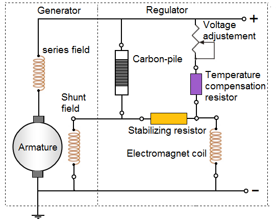
Voltage is controlled in an electromagnetic generator by controlling the field current, and one of the earlier types of voltage control, one which still finds some application, is the carbon-pile voltage regulator.
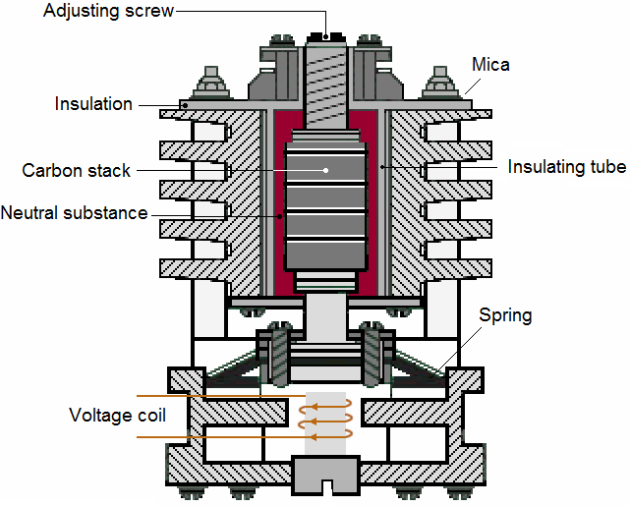
Thin discs of pure carbon are stacked inside a ceramic tube and pressure is applied to the stack by a spring. An electromagnet acts on an armature attached to the spring, so that the total force will be proportional to the output voltage.
The carbon pile voltage regulator depends on the resistance of a number of carbon disks arranged in a pile or stack. The resistance of the carbon stack varies inversely with the pressure applied.
When the stack is compressed under appreciable pressure, the resistance in the stack is less.
When the pressure is reduced, the resistance of the carbon stack increases, because there is more air space between the disks, and air has high resistance.
Figure below represents a cross section of a carbon-pile regulator.
Pressure on the carbon pile depends upon two opposing forces:
a spring and
an electromagnet.
When the output voltage rises, the pull of the electromagnet increases and overcomes some of the spring force, loosening the stack of carbon discs and increasing its resistance.
This increased resistance decreases the field current and lowers generator output. As output voltage drops, current through the electromagnet decreases, and so does its pull on the spring which allows it to force the discs tighter together.
This decreases the resistance of the pile and increases the generator field current
Carbon-pile regulators are used with relatively high-output generators and often on multi-engine aircraft. The paralleling system with a carbon-pile regulator maintains a balance between the loads of the generators. This is done by using a paralleling coil on the
regulators to increase voltage on the generator carrying less than its share of the load, and to decrease voltage on the one carrying most of the load.
2. CONTROL OF ALTERNATORS:
2.1. Vibrator-type:
The field excitation of an alternator is taken from regulated voltage rather than directly from the source, so the maximum amount of current the alternator can produce is automatically limited, and there is no need for a current limiter as we used with a generator.
Two controls are needed however:
a voltage regulator to control the amount of current flowing in the rotor, or field, and
a field relay to open the field circuit when the generator is not operating.
This prevents the battery discharging through the field.
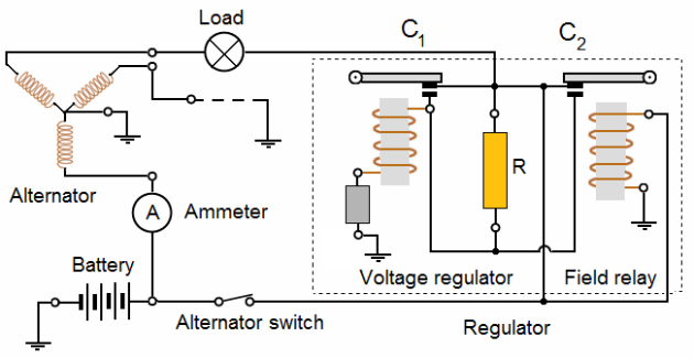
Figure below is a schematic of a vibrator-type control for an alternator.
Field relay modes:
When the alternator switch is closed, the field relay is energized. It allows current to flow from the battery, through the field relay contacts. Now, C2 is closed. It is the normal mode of the field relay.
If reverse current occurs the field relay is immediately de-energized and C2 is open. It is the abnormal mode of the field relay.
Voltage regulator operation:
In normal mode of the field relay, the alternator can begin to produce electricity. The contact C1 is closed. Current flows through the field.
When the voltage rises to the regulated value, the voltage regulator coil opens the contact C1. The field current must now flow through the resistor R. The field is now de-energized. C1 is closed.
As long as the alternator is operating in the lower end of the regulated voltage range, the points are vibrating between the lower and center contacts, allowing the current to go directly to the field or to pass through the resistor.
As the alternator speed increases, the points are pulled down so that as they vibrate, they alternate between placing the resistor in the field and grounding the field. With both ends of the field grounded, there is no current in the field and voltage drops off immediately.
2.2. Transistorized voltage regulator:
Vibrating points are a source of mechanical problems, as well as arcing which can cause radio interference. The advent of the transistor and its use as a switching device has made it possible to control voltage of alternators without the use of the vibrating points.
A transistor can be used as a switch and accomplish the same thing as the points. Let's review the transistor to see just how it works.
Field relay modes:
When the alternator switch is closed, the field relay is energized. It allows current to flow from the battery, through the field relay contacts. Now, C1 is closed. It is the normal mode of the field relay.
If reverse current occurs the field relay is immediately de-energized and C1 is open. It is the abnormal mode of the field relay.
Voltage regulator operation:
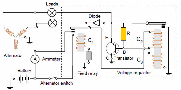
A practical circuit of a transistorized voltage regulator is seen in Figure.
When the alternator switch is closed, the field relay C1 is energized, closing its contacts, and allowing current to flow into the field through the loads to ground through the transistor.
The transistor is conducting between its emitter and collector, because the voltage regulator contacts are closed and emitter-base current is flowing to ground through them. The output voltage will rise until the combined pull of C2 and C3 becomes strong enough to open the voltage regulator points.
Now, no base current can flow and the transistor stops conducting, so there is no more field current.
While the points are open, current will still flow through C3 and its magnetic field will still be active; but the circuit through C2 is broken and its field instantly collapses, so the points will close rapidly.
When the points close, the total pull will increase rapidly because of the two coils. This second winding is appropriately called an accelerator winding, diode D1 is used to prevent voltage surge (which occurs when current abruptly stops flowing through the field winding) from damaging the transistor.
When the surge occurs, it causes the diode to break down and conduct through to the opposite side of the field until the voltage drops to a value that will not damage the transistor.
Resistor R1 is in the circuit to help keep the transistor shut off when the contact points are open.
2.3. Transistor voltage regulator:
While the transistorized voltage regulator uses a transistor to actually control the flow of field current, an electromagnetic coil is used to sense voltage. Transistor regulators, on the other hand, are fully solid-state; that is, there are no moving parts in the regulator itself. Voltage is sensed by a special kind of device called a zener diode.
Field relay modes:
When the alternator switch is closed, the field relay is energized. It allows current to flow from the battery, through the field relay contacts. Now, C is closed. It is the normal mode of the field relay.
If reverse current occurs the field relay is immediately de-energized and C is open. It is the abnormal mode of the field relay.
Voltage regulator operation:
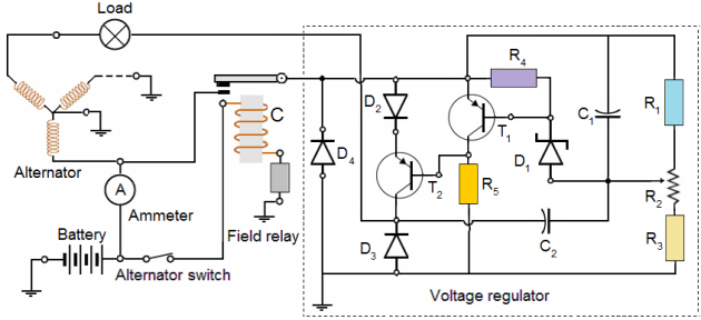
In Figure below we have the complete circuit of a basic transistor voltage regulator.
The output of the alternator is across the voltage divider made up of resistors R1, R2, and R3. The zener diode D1 senses the voltage drop across R1 and part of R2.
When the voltage across it is low, there will be no current flow through the base of transistor T1, called the driver transistor. With no base current, there will be no emitter-corrector current and no voltage drop across R5. Base current can flow through transistor T2 and it will conduct. T2, you will notice, is the output transistor and is in series with the alternator field.
With the field receiving its full field current, output voltage will rise, and at the point of regulation, there will be enough voltage across the zener diode to cause it to conduct.
When it conducts, base current flows in transistor T1, which causes an emitter-collector current to flow through resistor R5. The voltage built up across R5 brings the base of transistor T2 to the same voltage as its emitter and shuts it off, so no field current can flow through T2, and the alternator output voltage drops off.
Diode D2 provides a constant voltage drop, so the emitter of transistor T2 will be sufficiently lower than the line voltage for the current through resistor R5 to be able to bring the base voltage of T2 up to that of its emitter and shut it off.
Diode D3 protects the transistors against voltage surges when the field current is suddenly stopped. The rapid collapse of the field will induce a voltage high enough to damage the transistors, but before it rises to a dangerous value, D3 will break down and conduct it to ground.
Diode D4 is a transient suppression diode that protects the transistors from any externally generated voltage surges, and capacitors C1 and C2 smooth out pulsations and cause the regulator to operate more smoothly.
