DESCRIPTION AND OPERATION
1. INVERTERS:
An inverter is used in some aircraft systems to convert a portion of the aircraft's DC power to AC. This AC is used mainly for instruments, radio, radar, lighting, and other accessories. These inverters are usually built to supply current at a frequency of 400 cps, but some are designed to provide more than one voltage; for example, 26 volt AC in one winding and 115 volts in another.
There are two basic types of inverters: the rotary and the static. Either type can be single phase or multiphase. The multiphase inverter is lighter for the same power rating than the single phase, but there are complications in distributing multiphase power and in keeping the loads balanced.
1.1. Physical principles:
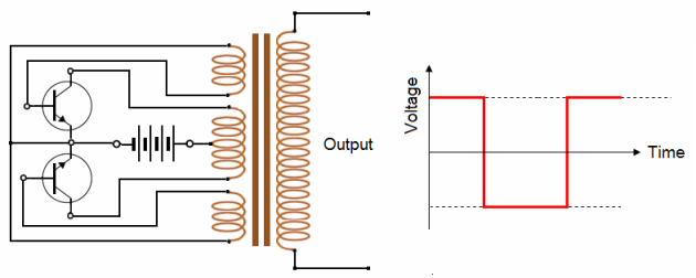
In one simple inverter circuit, DC power is connected to a transformer through the centre tap of the primary winding.
A switch is rapidly switched back and forth to allow current to flow back to the DC source following two alternate paths through one end of the primary winding and then the other.
The alternation of the direction of current in the primary winding of the transformer produces alternating current (AC) in the secondary circuit
The electromechanical version of the switching device includes two stationary contacts and a spring supported moving contact.
The spring holds the movable contact against one of the stationary contacts and an electromagnet pulls the movable contact to the opposite stationary contact. The current in the electromagnet is interrupted by the action of the switch so that the switch continually switches rapidly back and forth.
As they became available with adequate power ratings, transistors and various other types of semiconductor switches have been incorporated into inverter circuit designs. Here the two push-pull transistors produce an output sinusoidal square voltage.
1.2. Fourier analysis:
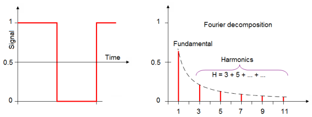
Using Fourier analysis, periodic waveforms are represented as the sum of an infinite series of sine waves. The sine wave that has the same frequency as the original waveform is called the fundamental component.
The other sine waves, called harmonics that are included in the series have frequencies that are integral multiples of the fundamental frequency.
The quality of output waveform that is needed from an inverter depends on the characteristics of the connected load. Some loads need a nearly perfect sine wave voltage supply in order to work properly.
Other loads may work quite well with a square wave voltage.
1.3. Three phase inverters:
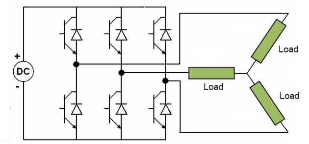
Three-phase inverters are used for variable-frequency drive applications and for high power applications. A basic three-phase inverter consists of three single-phase inverter switches each connected to one of the three load terminals.
For the most basic control scheme, the operation of the three switches is coordinated so that one switch operates at each 60 degree point of the fundamental output waveform.
This creates a line-to-line output waveform that has six steps. The six-step waveform has a zero-voltage step between the positive and negative sections of the square-wave such that the harmonics that are multiples of three are eliminated as described above.
2. TRANSFORMER RECTIFIER UNITS (TRUs):
2.1. Transformer principle:
A transformer is composed of two or more circuits magnetically coupled together.
For instance, figure shows a simple transformer, made of two circuits, each of them having an inductor device wrapped around the same iron core.
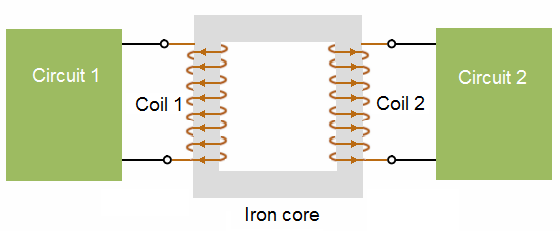
Circuit 1 is often an AC voltage source. Its “powered” wire coil is usually labelled the primary coil. Circuit 2 is often a load. Its “unpowered” coil is usually labelled the secondary coil.
The inductor coils are often called windings, for they are “wound” around the core material.
If a current flows through the coil 1, a time varying magnetic flux is produced and maintained within the core. This flux links and couples winding 2.
The same way, if a current flows through the coil 2, a time varying magnetic flux is produced within the core. This flux couples winding 1.
If there is a change in the current flowing in one of the coils, the flux generated within the core undergoes a change. This change in flux in the other coil induces a voltage across it.
This effect is called mutual inductance: A voltage is induced in one coil, due to a change in current in the other one.
In fact, a transformer transforms electrical energy (current in first coil) into magnetic energy (flux in core) which is transformed again into electric energy (voltage across second coil).
We know that self-inductance is measured in Henrys. This is also the case for mutual inductance. However, self-inductance is designated by the letter , whereas mutual inductance is symbolized by the letter M.
2.2. Real transformer (TRUs):
A real transformer is a transformer that does not reach the “ideal properties” of an ideal transformer:
The coils wrapped around the core do create leakage fluxes. Not all the flux generated by one winding will couple the other winding because of these leakage fluxes.
The windings of a real transformer have resistances.
The core of a real transformer has finite permeability.
The core is subjected to losses. As the magnetic field within the core reverses direction every half cycle of the applied voltage, following the hysteresis cycle, energy is dissipated.
The losses are proportional to the area of the hysteresis cycle :
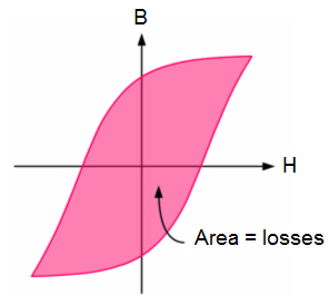
Remembering the relationship between the field intensity H (expressed in ampere-turns per meter, the magnetic flux density B (expressed in teslas T ) and the permeability of the material mu (expressed in tesla-meters per ampere-turns).
![]()
We deduce that if we want to lower the hysteresis losses, we can either operate at low flux densities in order to have B = 0. The core is also subjected to eddy currents.
These losses can be minimized by operating at low fluxes, by reducing the thickness in laminations (the iron core is actually made of many thin insulated sheets called laminations rather than a solid piece or by using a highly resistive material.
2.3. Aircraft transformers:
TRUs are probably the most frequently used method of power conversion on modern aircraft electrical systems.
Most aircraft have a significant 115 V 3-phase AC power generation capability inherent within the electrical system and it is usual to convert a significant portion of this to 28 V de by the use of TRUs.
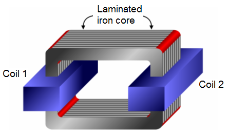
TRUs comprise star primary and dual star/delta secondary transformer windings together with 3-phase full wave rectification and smoothing to provide the desired 115 V AC/28 V DC conversion.
A typical TRU will convert a large amount of power, for example the Boeing 767 uses two TRUs each of which supply a rated load of 120 amps (continuous) with a five minute rating of 180 amps.
TRUs dissipate a lot of heat and are therefore forced air cooled. The Boeing 767 unit is packaged in a 6 MCU ARINC 600 case and weighs around 24 lb. TRUs are usually operated in isolation, however they may also be configured to operate in parallel in a similar way to the parallel operation of de generators.
2.4. Auto-transformer:
In certain parts of an electrical system simple auto-transformers may be used to provide a simple voltage step-up or step-down conversion. An example of this is the 115 V/28 V AC transformation used to provide 28 V AC aircraft lighting supplies direct from main 115 V AC supplies with the minimum of power conversion overhead.
Battery chargers share many of the attributes of TRUs and are in tact dedicated units whose function is purely that of charging the aircraft battery. In some systems the charger may also act as a standby TRU providing a boosted source of de power to the battery in certain system modes of operation.
Usually, the task of the battery charger is to provide a controlled charge to the battery without overheating and for this reason battery temperature is usually closely monitored.
3. RECTIFIERS:
3.1. Power diodes:
We saw that a semiconductor signal diode will only conduct current in one direction from its anode to its cathode (forward direction), but not in the reverse direction acting a bit like an electrical one way valve.
A widely used application of this feature is in the conversion of an alternating voltage (AC) into a continuous voltage (DC).
Small signal diodes can be used as rectifiers in low-power, low current (less than 1-amp) rectifiers or applications, but were larger forward bias currents or higher reverse bias blocking voltages are involved the PN junction of a small signal diode would eventually overheat and melt so larger more robust power diodes are used instead.
Power diodes are designed to have a forward "ON" resistance of fractions of an Ohm while their reverse blocking resistance is in the mega-Ohms range.
Some of the larger value power diodes are designed to be "stud mounted" onto heat sinks reducing their thermal resistance to between 0.1 to 1oC/Watt.
If an alternating voltage is applied across a power diode, during the positive half cycle the diode will conduct passing current and during the negative half cycle the diode will not conduct blocking the flow of current. Then conduction through the power diode only occurs during the positive half cycle and is therefore unidirectional i.e. DC as shown.
3.2. Half-wave rectifier:
First alternance:

During the half cycle when the diode is forward-biased.
![]()
Where VT is the threshold voltage of the diode.
Second alternance:
During the half cycle when the diode is reverse-biased Vout = 0.
Alternative current :
3.3. Full-wave rectifier:
Half-wave rectifiers have some applications :
However, full-wave rectifiers are the most commonly used ones for DC power supplies.
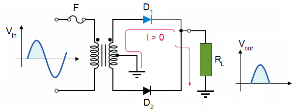
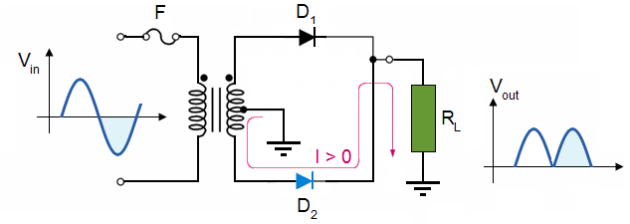
A full-wave rectifier is exactly the same as the half-wave, but allows unidirectional current through the load during the entire sinusoidal cycle (as opposed to only half the cycle in the half-wave).
![]()
During positives half-cycles, D1 is forward-biased and D2 is reverse-biased.
![]()
During negatives ha
lf-cycles, D1 is reverse-biased and D2 is forward-biased.
3.4. Bridge rectifiers:
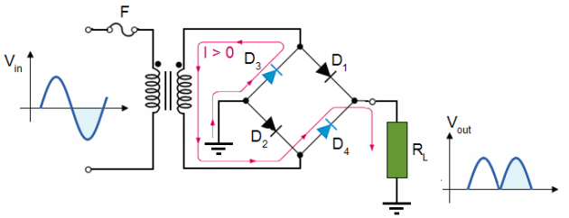
A bridge rectifier can be made using four individual diodes, but it is also available in special packages containing the four diodes required. It is called a full-wave rectifier because it uses all the AC wave (both positive and negative sections).
1.4 V is used up in the bridge rectifier because each diode uses 0.7 V when conducting and there are always two diodes conducting, as shown in the diagram below. Bridge rectifiers are rated by the maximum current they can pass and the maximum reverse voltage they can withstand (this must be at least three times the supply RMS voltage so the rectifier can withstand the peak voltages).
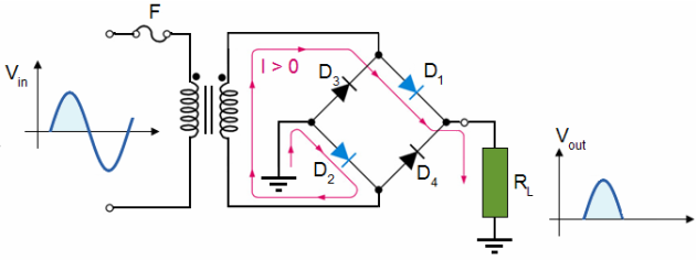
During positives half-cycles of the input, D1 and D2 are forward-biased and conduct the current. D3 and D4 are reverse-biased and don't conduct.
During negatives half-cycles of the input, D1 and D2 are reverse-biased and doesn't conduct the current. D3 and D4 are forward-biased and conduct.
3.5. Adding a smoothing capacitor:
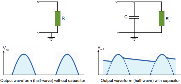
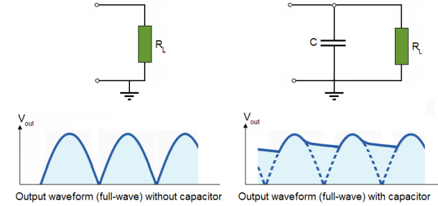
Smoothing is performed by a large value electrolytic capacitor connected across the DC supply to act as a reservoir, supplying current to the output when the varying DC voltage from the rectifier is falling.
The diagram shows the unsmoothed varying DC (dotted line) and the smoothed DC (solid line).
The smoothing capacitor converts the wave rippled output of the rectifier into a smooth DC output voltage.
Generally for DC power supply circuits the smoothing capacitor is an Aluminium Electrolytic type that has a capacitance value of 100uF or more with repeated DC voltage pulses from the rectifier charging up the capacitor to peak voltage.
However, their are two important parameters to consider when choosing a suitable smoothing capacitor and these are its Working Voltage, which must be higher than the no-load output value of the rectifier and its Capacitance Value, which determines the amount of ripple that will appear superimposed on top of the DC voltage. Too low a value and the capacitor has little effect but if the smoothing capacitor is large enough (parallel capacitors can be used) and the load current is not too large, the output voltage will be almost as smooth as pure DC.
As a general rule of thumb, we are looking to have a ripple voltage of less than 100mV peak to peak.
Half-wave rectifier:
The capacitor discharges through after peak of positive alternation when the diode is reverse-biased. The discharging occurs during the portion of the input voltage indicated by the solid blue curve.
The capacitor charges back to peak of input when the diode becomes forward-biased.
This charging occurs during the portion of the input voltage indicated by the solid blue curve.
Full-wave rectifier:
A capacitor-input filter will charge and discharge such that it fills in the “gaps” between each peak. This reduces variations of voltage. This voltage variation is called ripple voltage.
The advantage of a full-wave rectifier over a half-wave is quite clear. The capacitor can more effectively reduce the ripple when the time between peaks is shorter.
3.6. Quality of voltage regulation:
The quality of voltage regulation is measured by two means:
Line regulation: how much change occurs in the output voltage for a given change in input voltage.
Line regulation =
 .
.
Load regulation: how much does the output voltage change over a certain range of current values: minimum (no load, NL) to maximum current (full load, FL).
Load regulation =


