DESCRIPTION AND OPERATION
The generation and conversion of power once accomplished requires a means of distributing it throughout the aircraft. Associated with the distribution function is the need to protect the electrical system from fault conditions.
The general principle which applies to protection is that it is the busbar/distribution system which is protected and not the electrical service/load. The prime aim of the protection is to minimize the loss of services and functions following a fault condition.
Electrical circuit protection devices are installed primarily to protect circuit wiring. To do this adequately, the protection devices should be located as close as possible to the electrical power source bus. Two types of circuit protection devices that are used on aircraft are:
fuses and
circuit breakers.
A current limiting device should open an electrical circuit before its conductors become hot enough to emit smoke. In order to achieve this, a circuit breaker or fuse is selected with time/current characteristics that fall below that of the associated conductor.
Circuit protection should be matched to conductor requirements in order to obtain maximum utilisation of the equipment operated by the circuit.
1. FUSES:
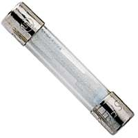
A fuse is simply a piece of low-melting-point alloy encased in a glass tube with metal contacts on each end. It is placed in the circuit, usually at the bus bar, so all of the current flowing to a circuit must pass through it. If too much current flows, the link will melt and open the circuit. To restore the circuit, the blown fuse must be replaced with a new one.
There are four types of fuses used in aircraft circuits:
Regular glass tubular fuse,
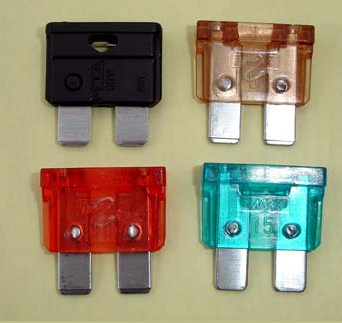
Blade fuses,
Slow-blow fuse and
Current-limiter fuse.
1.1. The regular glass tubular fuse:
The regular fuse has a simple narrow strip of low-melting-point material that will melt as soon as an excess of current flows through it.
1.2. Blade fuse:
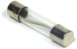
1.3. The slow-blow fuse:
The slow-blow fuse has a larger fusible element that is held under tension by a small coil spring inside the glass tube.
This fuse will pass a momentary surge of high current such as that when the switch in a lighting circuit is closed, but it will soften under a sustained current flow in excess of its rating. The spring will pull the fusible link in two, opening the circuit. Aircraft fuses are rated according to the maximum continuous amperage they can carry.
For certification of a normal, utility, acrobatic, or commuter category aircraft, CFR 14 Part 23 requires that a spare fuse of each rating, or 50% of each rating of accessible fuses, whichever is greater, be carried and readily accessible in flight.
CFR 14 Part 91 requires the operator of an aircraft, using fuses as protective devices and flying at night, to carry a spare set. The spare set may consist of a complete replacement set of fuses or a quantity of three replacement fuses for each kind required.
Fuses that are accessible by maintenance personnel are found on some aircraft.
1.4. The current-limiter fuse:
These fuses, commonly called current-limiters, are often used to isolate a complete distribution bus in the event of a short to that bus. In the event the current limiter opens, the pilot would continue the flight without use of the isolated bus and have the problem corrected upon landing.
A current-limiter operates in the same manner as a fuse and is often used to protect an entire electrical bus. The center section of the limiter has a clear inspection window where the condition of the fusible material can be visually inspected.
Fuses are also used in the electrical system to protect the circuits and equipment from electrical overload. Spare fuses of the proper amperage limit should be carried in the aircraft to replace defective or blown fuses.
Placards at the fuse or circuit breaker panel identify the circuit by name and show the amperage limit.
2. CIRCUIT BREAKERS:
Circuit breakers are used rather than fuses because it is so much easier to restore a circuit in flight by simply resetting the circuit breaker than it is to remove and replace a fuse.
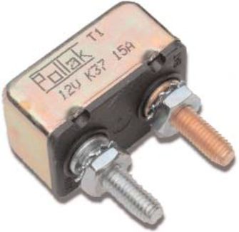
Here are two basic types of circuit breakers used in aircraft electrical systems:
those that operate on heat, and
those that are opened by the pull of a magnetic field.
Most aircraft breakers, however, work on the principle of heat. When more current flows than the circuit breaker is rated for, a bimetallic strip inside the housing warps out of shape and snaps the contacts open, disconnecting the circuit.
Most circuit protection for modern aircraft is provided by circuit breakers that can be reset in flight. The push-pull type is shown in the upper panel, with the push-to-reset type in the lower panel.
There are basic configurations of circuit breakers used in aircraft electrical systems:
the push-to-reset,
the push-pull type and
the toggle type.
a) The button of the push-to-reset type of circuit breaker is normally in, and it pops out only when the circuit has been overloaded. This type of circuit protection device cannot be used as a switch, as there is no way to grip the button to pull it out.
b) The push-pull-type circuit breaker has a small lip that can allow the breaker to be pulled to open the circuit. Normally these circuit breaker buttons are in, but if a breaker is overloaded, the button pops out and is easily identified.
Many of these circuit breakers have a white band around the button that is visible when the breaker has popped. This type of circuit breaker should be used as a switch only for isolating a circuit for maintenance purposes.
c) The toggle-type circuit breaker is normally used as a control switch as well as a circuit breaker. When the toggle is up, the circuit is closed, but if the circuit is overloaded, the breaker will pop partially down. To restore the circuit, the toggle is moved all the way down and then back up.
Typical circuit breaker :
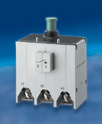
Circuit breakers perform the function of protecting a circuit in the event of an electrical overload. Circuit breakers serve the same purpose as fuses or current limiters. A circuit breaker comprises a set of contacts which are closed during normal circuit operation.
The device has a mechanical trip mechanism which is activated by means of a bi-metallic element.
When an overload current flows the bi-metallic element causes the trip mechanism to Activate, thereby opening the contacts and removing power from the circuit. A push button on the front of the unit protrudes showing that the device has tripped. Pushing in the push button resets the breaker but if the fault condition still exists the breaker will trip again.
Physically pulling the button outwards can also allow the circuit breaker to break the circuit, perhaps for aircraft maintenance reasons.
Circuit breakers are rated at different current values for use in differing current carrying circuits. This enables the trip characteristic to be matched to each circuit. The trip characteristic also has to be selected to co-ordinate with the feeder trip device upstream.
Circuit breakers are used by the hundred in aircraft distribution systems; it is not unusual to find 500 to 600 devices throughout a typical aircraft system.
3. POWER SWITCHING:
In order to reconfigure or to change the state of a system it is necessary to switch power at various levels within the system. At the high powers which prevail at the primary power part of the system, switching is accomplished by high power electromagnetic devices called contactors. These devices can switch hundreds of amps and are used to switch generator power on to the primary busbars in both DC and ac systems.
Note:
For switching currents below 20 amps or so relays are used. These operate in a similar fashion to contactors but are lighter, simpler and less expansive. Relays may be used at certain places in the primary electrical system.
However relays are more likely to be employed for switching of medium and high power secondary aircraft loads or services.
For lower currents still simple switches can be employed. These switches may be manually operated by the crew or they may be operated by other physical means as part of the aircraft operation. Such switches are travel limit switches, pressure switches, and temperature switches and so on.