GENERAL ENGINE PARAMETERS
“Control parameters” or “main parameters” and “monitoring parameters.
This classification of engine parameters in two categories is not rigid and may vary depending on manufacturers.
Control parameters are primordial for the crew. These parameters express the engine performance.
Monitoring parameters help the crew take care of the correct engine operation.
All these indications provide to the crew a good idea of the engine “health”.
Engine parameters may be displayed on analogue or numerical indicators.
a) Control parameters:
We find:
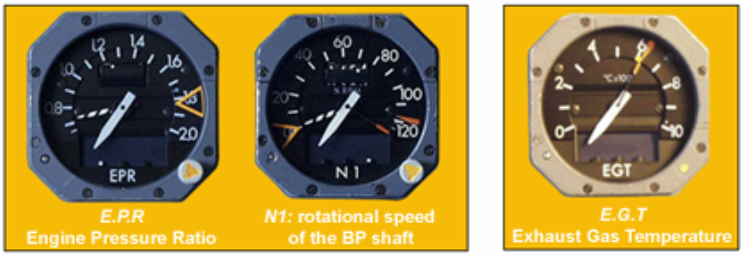
the EPR (Engine Pressure Ratio),
the EGT (Exhaust Gas Temperature),
the FF (Fuel Flow),
and N1 (rotational speed of the brake power – BP - shaft).
and N2 (rotational speed of the HP shaft).

These parameters express the engine performance.
b) Monitoring parameters:
These parameters help the crew take care of the correct engine operation.
They indicate the fuel consumption, oil quantity, oil pressure, oil temperature, oil filter clogging, fuel filter clogging, engine vibration and the nacelle temperature.

The indications provided by engine parameters must be reliable: they are the interface between the engine and the crew who counts entirely on them to evaluate the engine performances and behavior.
The indications provided by engine parameters must be precise; the crew could not trust approximate indications; a wrong indication may be more prejudicial than no indication at all.
The display of engine parameters must be instantaneous. A slow display or a shift between the change of a parameter value and its indication in the cockpit may have serious consequences.
Example: when the pilot keeps a close eye on a rising EGT, a shift of the indication might make him believe that the maximum EGT is not yet reached, whereas actually, the engine is already overheating.
1. LOCATION:
The indications provided by engine parameters are always in the centre of the cockpit instrument panel; thus, their reading is easy for the pilot as well as for the co-pilot.
Among the control parameters, which indicates that the engine thrust is the most important; this is why the indication of EPR or N1 is right at the top.
This layout always applies, whatever the type of indicator might be: old dial and pointer indicators, or new electronic displays (CRT: cathode-ray tubes and LCD: liquid crystal displays).
Note:
On some aircrafts (B767) equipped with an electronic display, a standby display of the engine control parameters may be found on an additional indicator (standby indicator).


On aircrafts having on board a flight engineer (OMN), all the engine monitoring parameters and some control parameters are displayed by indicators on the flight engineer's panel. However, all the control parameters are displayed on the cockpit instrument panel, including those displayed in double on the flight engineer's panel.
2. DESCRIPTION:
Engine parameters may be displayed on analogue or numerical indicators. In an analogue indicator, an index or a pointer moves to indicate a value, graduated on the periphery of the dial.
There are two types of numerical indicators: dial indicators and electronic indicators.

In a digital (numerical) display of a dial indicator, small drums, graduated from 0 to 9 on the circumference, rotate and form a number readable through a dial window; the same analogue signals which actuate the pointer or the index of an analogue indicator, drive the digital display drums of a dial indicator.
Electronic indicators are divided into two main categories: consisting of a cathode-ray tube (CRT) and of liquid crystal displays (LCD).
These two categories of indicators are used often on modern aircrafts; they are more reliable and more precise than conventional dial indicators.
Electronic indicators receive video signals and can replace many indicators in only one instrument; on the other hand, these electronic screens need an air cooling, which is not required for conventional indicators.
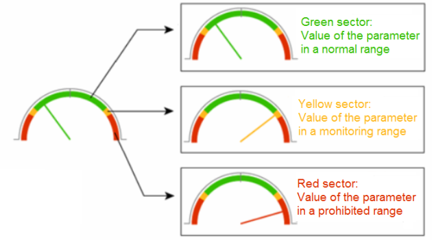
The engine parameters indicators may have coloured sectors, allowing the pilot to determine by a simple glance if everything is normal.
These coloured sectors may be found on conventional analogue indicators, as well as on electronic indicators.
Example:
the pointer in the green sector means that the value of this parameter is in a normal range.
the pointer in the yellow sector means that the value of this parameter is in a range requiring an attentive monitoring by the crew.
the pointer in the red sector means that the value of this parameter has reached a prohibited range, very abnormal even dangerous requiring an immediate action by the crew.