CONTROL PARAMETERS
1. EXHAUST GAS TEMPERATURE (EGT) – INTERSTAGE TEMPERATURE SYSTEMS:
1.1. EGT system:
The EGT represents the turbine temperature. It is a very important parameter which warns the crew when the temperature is close to the mechanical limits of the turbine and the combustion chamber.
Several temperature sensors, generally thermocouples in chrome/nickel and nickel/aluminium, are laid on the periphery of the conduit, near the turbine outlet.
These probes pass on an average temperature to the EGT indicator, graduated in degrees Celsius and placed on the instrument panel.
1.2. EGT indication:
This fundamental parameter is always indicated to the cockpit.
In fact, the highest temperature of the turbojet is located at the input of the high pressure turbine, but the “measured” temperature is downstream: either between the stages of the HP and LP turbines, or, generally, at the exit of the LP turbine.
Manufacturers have adopted this solution because the exposure of thermocouple probes to very high temperatures is not easily achievable. As the fall of temperature through the turbine stages is established with precision, the “measured” temperature, downstream from the turbines, is likely to be representative of the turbine inlet temperature.
Depending on constructions, from 4 to 11 thermocouple probes laid out in the periphery of the conduit may be found; these thermocouples are made of two wires of different material, generally a nickel-chromium alloy for the first one and a nickel-aluminium alloy for the other one. Their tip is welded, inside an openwork tube allowing hot gases to cross it.
All the probes are connected in parallel, in order to send a signal of average temperature.
On modern engines equipped with an electronic engine controller (EEC or ECU), the EGT probes may have two thermocouples, one for each channel of the calculator; or a total of eight EGT probes, with a distribution of four probes for each channel of the calculator.
The electronic engine controller transforms the signal of average temperature into digital data sent to the engine parameters display system (ECAM or EICAS).
→ EGT system and indication:

2. ENGINE PARAMETERS:
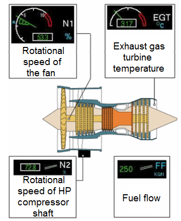
2.1. Engine speed (N2):
N2 is the rotational speed of the high-pressure compressor shaft. Is used by the pilot to control the engine performances. N2 is expressed as a percentage of the rated rotational speed. The transmitter is generally a tachometric generator driven by the accessory gear box.
The rotational speed of the HP spool is always indicated: N2 for twin spool turbojets, N3 for triple spool turbojets (Rolls Royce).
N1, the symbol of the rotational speed of the low pressure compressor shaft, is used on turbojets GE and CFM to indicate the thrust.
On a twin spool turbojet, the N1 indication represents, expressed as a percentage, the rotational speed of the fan.
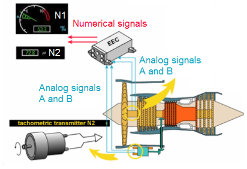
The speed signal can come from a small tachometric generator driven by the AGB (Accessory Gear Box), or from a phonic wheel sensor located on the AGB. In both cases, two analogue signals are available; as for N1, they are digitized by the calculator (ECU or EEC) before being used by the display system (ECAM or EICAS).
2.2. Engine pressure ratio (EPR):
This parameter is used on turbojets P&W and RR to indicate the thrust. A probe measures the total pressure Pt2 in the air intake of the engine and another probe measures the total pressure Pt7 (or Pt5) at the exit of the turbine in the ejection duct. A device carries out the metric quotient Pt7 / Pt2 and this signal is displayed on the EPR indicator.
When the EPR is not the significant thrust control parameter, the speed transmitter N1 provides an indication of the rotational speed of the fan, which is a linear function of the engine thrust.
2.2.1. EPR pressure data:
All the instruments which display the engine parameters in the cockpit receive the data collected by various sensors, probes, detectors or transmitters located on the engine.
For the EPR, the oil pressure, oil low pressure warning, fuel filter clogging warning and the fuel pressure.
This parameter measures the thrust produced by the engine (on some engines, N1 is the thrust parameter).
Pipings send the total pressures Pt2 and Pt7 to the electronic engine controller (EEC or ECU).
The computer converts these pressures into electric signals, calculates the “EPR” value and sends it to the engine parameters display system (ECAM or ECAS).
On some engines, the same probe combines the sampling of the Pt2 air intake total pressure with the Tt2 air intake total temperature; in the same way, a same probe can record the Pt7 total pressure and the EGT in the turbine outlet.
2.2.2. EPR temperature data:
On some engines, the same probe combines the sampling of the Pt2 air intake total pressure with the Tt2 air intake total temperature; in the same way, a same probe can record the Pt7 total pressure and the EGT in the turbine outlet.
On modern aircrafts, the speed sensor sends two analogue signals; one for each channel of the calculator, which digitizes them before passing them on to the display system (ECAM or EICAS).
2.3. Oil quantity, pressure and temperature:
As this system is very important for the turbojet operation, it is imperative that some parameters might be available on the instrument panel, so that the crew may keep a close eye on them.
In addition to oil pressure which determines the quantity of oil delivered by the lubrication burners to the bearings, oil temperature is one of the factors determining the oil lubricating power and its cooling capacity; it is therefore an important parameter.
2.3.1. Oil quantity:
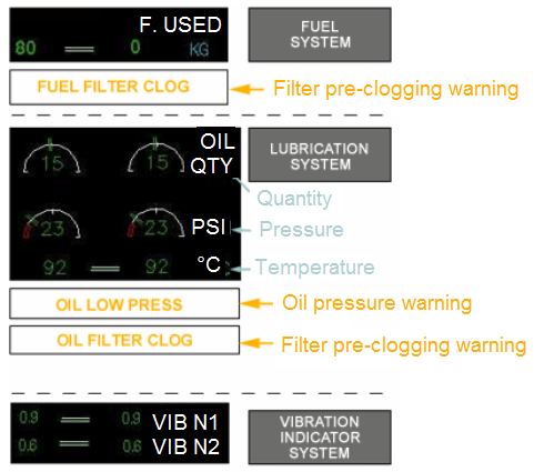
An indicator graduated in quarter (QTY) displays the volume of oil remaining in the tank. This indication allows the crew to watch oil consumption.
2.3.2. Oil pressure:
This parameter makes it possible to appreciate the level of lubrication of the bearings and other parts of the engine. The oil pressure is generally measured on the outlet side of the pump and is indicated in PSI or PSID.
2.3.3. Oil temperature:
In addition to oil pressure which determines the quantity of oil delivered by the lubrication burners to the bearings, oil temperature is one of the factors determining the oil lubricating power and its cooling capacity; it is therefore an important parameter.
The indicator, graduated in degrees Celsius, shows to the crew if the lubrication system functions in a range of normal temperatures.
Complementary to the oil temperature, these two parameters are crucial for the monitoring of the engine; they are always indicated.
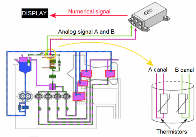
A pressure transmitter sends an analogue signal to the electronic engine controller (EEC or ECU) where it is digitized before being used by the electronic display system.
On some modern installations, the oil pressure transmitter comprises two LVDT' S (Linear Variable Differential Transformer) which send a signal of oil pressure to each of the two EEC (or ECU) channels.
Depending on installations, the oil temperature sensor can be located in the “pressure” circuit or in the “scavenge” circuit of the engine lubrication system.
The probe is composed of two thermocouples or two thermistors, one for each channel of the EEC or ECU calculator which transforms the signal of temperature into digital data usable for the ECAM or EICAS display system.
This parameter is seldom displayed in modern cockpits; however, the maintenance engineer is able to find this information while reaching pages dedicated to the maintenance of the electronic display system.
A probe with two channels measures the fuel temperature at the exit of the fuel/oil heat exchanger.
Each channel provides a signal of temperature to each of the two channels of the electronic engine controller.
2.3.4. Oil pressure warning:
In addition to the indication of oil pressure, most aircrafts also have an oil “low pressure” warning. This may be displayed by a red indicator, a luminous indicator, captioned “oil press”, or by a message written on an electronic screen.
This warning lights up as soon as oil pressure falls below a given value.
A “low oil pressure” switch closes as soon as oil pressure decreases below a predetermined value, and sends a warning to the engine parameters display system.
This signal actuates a sound alarm in the cockpit and, depending on installations, the oil pressure indication on the electronic display starts blinking and/or changing colour (red).
It should be noted that this switch, while being closed, does not send any signal to the EEC (or ECU) which in addition receives an oil pressure signal.
2.3.5. Filter pre-clogging warning:
On some oil circuits, the oil filter is equipped with a differential pressure switch (P switch). It lights an indicator or generates a warning message which means that the oil filter starts clogging, as the differential pressure reaches a given value.
2.4. Fuel pressure temperature and flow:
Besides the “fuel flow” and “overall consumption” indication which are displayed in all cockpits, some installations may comprise of one or more complementary indications:
Fuel pressure,
Fuel temperature,
Fuel filter pre-clogging warning.
2.4.1. Fuel pressure:
Aircrafts which have on board a flight engineer (OMN) may be equipped with a fuel pressure gauge on the mechanic's panel, graduated in PSI, which expresses the pressure recorded between the two stages of the fuel pump.
On some installations (generally on engines not equipped with an electronic engine controller), an indication of fuel pressure is displayed in the cockpit. A pressure transmitter, located in the centrifugal pump outlet (boost pump), sends this information, displayed in an analogue or digital form.
This indication is sometimes associated with a low pressure warning; in this case, the fuel pressure display blinks when its value is lower than a predetermined one.
2.4.2. Fuel temperature:
This indication may still be found on some installations; the signal of temperature comes from a probe generally located at the input of the fuel regulator. The indicator is graduated in degrees Celsius.
2.4.3. Fuel filter pre-clogging warning:
A differential pressure switch (ΔP switch) on the fuel filter, closes as soon as ΔP is reached and lights a warning signal or generates a warning message on an electronic screen.
This warning means that the fuel filter starts clogging, generally due to a fuel icing in its infancy; in this case the crew actuates the “fuel reheating” system when this function is not automatic.
The switch closes for a differential pressure lower than the by-pass valve opening pressure; this generates a warning message “fuel filter bypass” (derivation) or “fuel filter clog” (filling), in spite of the fact that the filter by-pass valve is not yet open. It is the reason why this warning is called “pre-clogging warning”.
2.4.4. Fuel flow:
This indication provides the crew with important information dealing with the engine efficiency and power; it is the instantaneous consumption in kilograms per hour (KPH) or pounds per hour (PPH) which is displayed. A flow transmitter, generally located after the HP fuel shut-off valve, measures the fuel mass flow rate and sends it to the indicator; this same information is used by the used fuel indicator.
2.5. Manifold pressure:
It is the absolute pressure of the fuel/air mixture inside the intake manifold On airplanes that are equipped with a constant-speed propeller, power output is controlled by the throttle and indicated by a manifold pressure gauge.
The gauge measures the absolute pressure of the fuel/air mixture inside the intake manifold and is more correctly a measure of manifold absolute pressure (MAP). At a constant RPM and altitude, the amount of power produced is directly related to the fuel/air flow being delivered to the combustion chamber.
As it increases the throttle setting, more fuel and air is flowing to the engine; therefore, MAP increases.
When the engine is not running, the manifold pressure gauge indicates ambient air pressure. When the engine is started, the manifold pressure indication will decrease to a value less than ambient pressure.
Correspondingly, engine failure or power loss is indicated on the manifold gauge as an increase in manifold pressure to a value corresponding to the ambient air pressure at the altitude where the failure occurred.
→ Engine power output is indicated on the manifold pressure gauge:
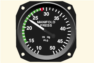
The manifold pressure gauge is color-coded to indicate the engine's operating range. The face of the manifold pressure gauge contains a green arc to show the normal operating range, and a red radial line to indicate the upper limit of manifold pressure.
For any given RPM, there is a manifold pressure that should not be exceeded. If manifold pressure is excessive for a given RPM, the pressure within the cylinders could be exceeded, thus placing undue stress on the cylinders. If repeated too frequently, this stress could weaken the cylinder components, and eventually cause engine failure.You can avoid conditions that could overstress the cylinders by being constantly aware of the RPM, especially when increasing the manifold pressure.
Conform to the manufacturer's recommendations for power settings of a particular engine so as to maintain the proper relationship between manifold pressure and RPM.
When both manifold pressure and RPM need to be changed, avoid engine overstress by making power adjustments in the proper order:
When power settings are being decreased, reduce manifold pressure before reducing RPM If RPM is reduced before manifold pressure, manifold pressure will automatically increase and possibly exceed the manufacturer's tolerances.
When power settings are being increased, reverse the order, increase RPM first, then manifold pressure.
To prevent damage to radial engines, operating time at maximum RPM and manifold pressure must be held to a minimum, and operation at maximum RPM and low manifold pressure must be avoided. Under normal operating conditions, the most severe wear, fatigue, and damage to high performance reciprocating engines occurs at high RPM and low manifold pressure.
2.6. Engine torque:
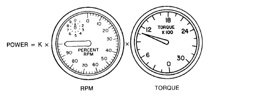
Engine torque is used to indicate the power that is developed by a turbopropeller engine. The torque display indicator is known as a torquemeter. The engine torque or turning moment is proportional to the horsepower and is transmitted through the propeller reduction gears.
→ K x RPM x Torque = Power (horsepower):
The engine operating condition, during which the torque indicating system is the most important, is called a “positive torque condition" Positive torque occurs when the engine is producing the power that drives the propeller. The torque indicating system is designed to measure the torque that is produced by the engine at a point between the engine and the propeller.
The actual horsepower at a given torque indication must be related to the effect of RPM. The formula illustrated in previos figure indicates that horsepower is a function of a mathematical constant (K) multiplied by the RPM and then by torque indication in foot-pounds. The K factor is a constant factor that does not change (K = 2π / 33,000)
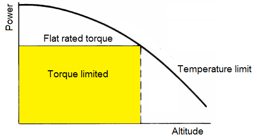
Exceeding the engine's temperature or the torque limitations may damage the aircraft or the engine. The curve in next figure indicates the torque and temperature operation of an engine on a typical installation. It can be seen that at a certain point the temperature limit will take precedence over the torque limit, as the aircraft reaches less dense air.
That point in pressure altitude or outside air temperature is a matter of the individual torque limit ratings applied by the airframe manufacturer.
Consequently, the pilot must monitor the applicable engine instruments and observe the flight manual limits.
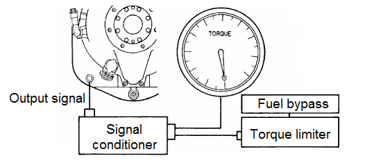
→ RPM-torque relationship. (Garrett):
A torque indicating system, which is basically an electronic system, is used by the Garrett TPE-331 engine.
The major components of this system, illustrated in Figure, includes a torque ring containing strain gages (sometimes referred to as the torque transducer) and an externally mounted signal conditioner, which sends a corrected signal to the cockpit torquemeter.
Wiring from the electrical connector mounted on the diaphragm will carry an electric signal externally from the gearbox to a signal conditioner. The signal conditioner is usually mounted somewhere in the nacelle adjacent to the engine.
Electric signals from the conditioner go to the torquemeter in the cockpit.
In addition to providing an indication of engine power, the torquemeter system may also be used to operate a torque limiter system, if one is installed, and to signal the automatic propeller feathering system if the torquemeter oil pressure falls due to an engine power failure.
2.7. Engine nacelle:
Although it should not be regarded as an engine control or monitoring parameter, the indication of nacelle temperature, when it exists, is displayed with the engine parameters.
The engine nacelles are ventilated and cooled by air bled from the fan; although they are fitted with fire and overheating detectors, an indication of the nacelle temperature may warn the crew about an abnormal rise in temperature, which would be due for example, to a small leakage in an air sampling system and which would not have set off the overheating warning.
The nacelle temperature indicator is graduated in degrees Celsius.
When this indication exists on the instrument panel, a temperature sensor located in a suitable location inside the nacelle sends a signal of temperature to the display system.
This probe has only one channel and contrary to the majority of the probes, the signal of temperature is not sent to the electronic engine controller (ECU or EEC).
In installations where the electronic engine controller supervises the cooling of the nacelle, it uses a signal of aircraft altitude rather than a signal of nacelle temperature.
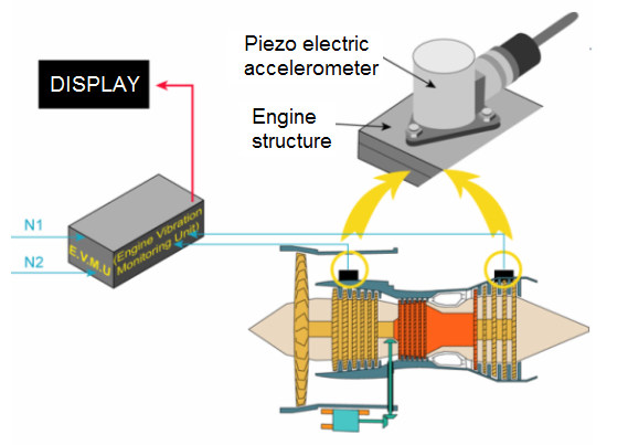
2.8. Engine vibrator indicator:
This system may allow the crew to identify an imminent failure before it might be detected, thanks to the indications of other engine parameters.
Detection of vibration from the very start can limit the damage caused by an abnormal engine wear.
On some aircrafts, the engine vibration detection and display system is called the “AVM system” for “Airborne Vibration Monitoring”.
Vibration pick-ups are installed in specific locations in the engine, and send signals to a “signal conditioner” which transforms the received signals so that they might be exploitable by the display system of engine parameters.
The display of the vibrations in the cockpit may be very variable with the installations:
the vibrations of N1 and N2 may be indicated simultaneously, or
a selector may allow to choose the display of one or another on a single indicator, or even, a single indicator automatically displays the vibration which is the highest.
The engine vibration monitoring system is composed of three main elements:
one to three vibration pick-ups,
a signals conditioner (or engine vibration calculator),
an indication intended to the cockpit.
The manufacturer determined the adequate location for the sensors on the structure of the engine, by taking into account its vibration sensitivity and some environmental considerations.
The sensors used on current engines are accelerometers made up of a piezoelectric crystal; a signal of electric charge, proportional to the forces applied by vibrations is generated and sent to the engine vibration monitoring unit (EVMU).
This EVMU receives the signals of all sensors, as well as the analogue signals of the speeds N1 and N2; it integrates these data and calculates the vibration level which is displayed in the cockpit.
The EVMU may also have other functions: it can calculate the vibration limits depending on engine speeds N1 and N2 and set off “caution” or “advisory” level warnings on screens ECAM or EICAS; it may also carry out calculations in connection with the fan balancing, and keep in memory all the data relating to the detected vibrations with a view of a later fault isolation and trend analysis.
2.9. Propeller speed:
Engines can be humbling because they are reminders that humans really can't fly—at least not for long—without some help. So, you've got to be good to your aircraft's engine. Here are some operating tips that will help keep your aircraft's engine running strong.

Many gauges on the control panel monitor engine functions. Two important engine instruments that measure engine power are the tachometer (which indicates engine speed as measured in revolutions per minute, or RPM), and the manifold pressure gauge (which indicates the pressure of air moving into the cylinders).
Most modern piston engine aircraft have two or three engine controls. Piston aircraft with a fixed-pitch propeller have two basic engine controls: a black throttle control, which has the most direct effect on power, and a red mixture control to adjust the air/fuel mixture as the airplane climbs and descends.
Aircraft with a constant-speed propeller also have a blue propeller control to adjust the propeller's rotation speed.
2.9.1. Throttle control:
The throttle determines how much power the engine can develop by controlling the amount of fuel and air entering the engine cylinders. When fully open, the throttle allows the maximum amount of fuel and air to enter the system to produce maximum power.
When the throttle is closed, only a small amount of fuel and air can enter the system, and the engine produces minimum power.
To open the throttle, push the throttle control in. To close the throttle, pull the control out.
The manifold pressure gauge on the instrument panel shows the pressure of the air moving into the engine's cylinders, and gives an approximate measurement of engine power. Generally speaking, the higher the manifold pressure, the more power you have available.
2.9.2. Mixture control:
Because an aircraft's engine operates over a wide range of altitudes, the fuel/air mixture can be adjusted for maximum efficiency as you climb into thinner air or descend into denser air.
A mixture that is too rich contains too much fuel for the existing atmospheric conditions and may cause the engine to run rough and lose power.
The solution is to "lean the mixture:" As you climb, make the mixture leaner by pulling the mixture control back until the needle on the exhaust gas temperature (EGT) gauge peaks, then push the mixture control forward a little.
Don't lean the mixture too much, though: a mixture that is too lean can cause the engine to overheat or result in a problem known as detonation, a sudden, strong, uncontrolled, and often damaging explosion of fuel and air within the cylinder.
2.9.3. Propeller control and managing power:
Piston engines are typically connected to a fixed-pitch or a constant-speed propeller.
2.9.3.1. Fixed-pitch propellers:
Fixed-pitch propellers are bolted directly to the crankshaft of the engine and therefore always turn at the same speed as the engine. A fixed-pitch prop is somewhat like a transmission with only one gear.
This configuration makes up for its lack of efficiency by being very simple to operate.
The only gauge that you need to monitor is the tachometer. Because the fixed-pitch propeller turns as fast as the engine, the engine's RPM is the best indicator of engine power. Use the tachometer to set your power during takeoff, cruising, and landing, the higher the RPM, the more power your engine is producing.
With a fixed-pitch propeller, managing power is simple. Push the throttle in, and RPM (and power) increases. Pull the throttle out, and RPM decreases. Be aware, however, that as airspeed increases, RPM tends to creep up, too. Monitor the tachometer carefully during descents at high speed to make sure that the RPM stays within limits.
2.9.3.2. Constant-speed propellers:
A constant-speed propeller has a governor that adjusts the angle of the blades to maintain the RPM you select. This type of propeller makes much more efficient use of the engine's power.
Adjusting the propeller in an airplane is very similar to using gears in a car. In low gears the engine turns fast to get you moving. Once you're underway, there's no need to use a lot of power, so you shift to a higher gear to make more efficient use of less power.
In an airplane, the propeller control changes the angle at which the propeller blades meet the air, which affects how fast the engine turns. The tachometer on the instrument panel shows how fast your engine is turning.
During takeoff and during landing (in case you need to abort and take off again) you'll need every bit of power your engine can develop. So during these two phases of flight, keep the propeller control pushed in: the angle of the blades will be low, slicing through the air easily so you can get the engine's full power (like using a low gear in a car).
During cruise, pull the propeller control out a bit: the angle of the blades will increase and take a bigger bite out of the air, making more efficient use of the engine's power . Any time you change the throttle setting a governor will automatically adjust the angle of the blades to maintain the propeller speed.
A constant-speed propeller makes power management a bit more complicated. You must monitor the manifold pressure gauge, controlled by the throttle, and the tachometer, which shows the propeller RPM. You adjust RPM with the prop control.
When using the throttle and prop controls, remember these basic rules to avoid overstressing the engine:
To increase power
Increase propeller speed by pushing the prop control forward.
Increase manifold pressure by pushing the throttle control forward.
To decrease power
Reduce manifold pressure by pulling the throttle control backward.
Decrease propeller speed by pulling the prop control backward.
2.9.4. Propeller control:
Sets the desired RPM of the propeller governor, which turn regulates the engine load as necessary to maintain the set RPM Once the RPM is set by the pilot, the governor adjusts engine load by increasing or decreasing propeller pitch by using engine oil pressure to move a piston in the propeller hub.
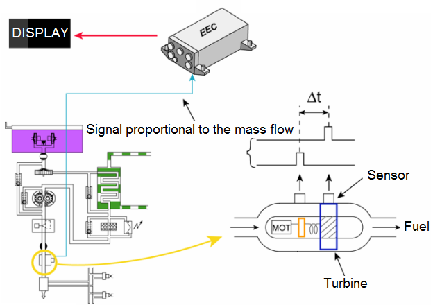
The fuel flow transmitter is located usually between the HP fuel shut-off valve and the fuel manifolds, near the injectors.
There are several types.
The most common is having a kind of propeller actuated at constant speed by an alternating three-phase electric motor; the rotation of the propeller imparts a whirling movement to the fuel passing in the conduit; this whirling movement creates a deflection on a turbine located downstream and maintained by one or more gauged springs.
The deflection angle of this turbine is proportional to the flow and the density of the fuel which crosses it; it is measured and produces an analogue electric signal proportional to the mass flow rate of the fuel.
Another type of fuel flow transmitter does not have any propeller driven by an electric motor, but only one turbine kept in rotation by one or more gauged springs, the angular deflection of which is measured.
In both cases, the signal is sent to the calculator; the EEC (or ECU) calculates the mass flow rate (expressed in Lbs/h or Kg/h) and passes it on to the ECAM or EICAS system for display. This same data is used to calculate the overall consumption (used fuel).