OPERATION AND USE OF PRECISION MEASURING TOOLS
One of the most important considerations in the manufacture, maintenance, and overhaul of machinery is measurement. The concept of interchangeable parts depends upon precision measurement.
The repair of an aircraft structure requires the measurement of damaged and replacement material.
1. RULES AND SCALES:
The most commonly used measuring instrument is the rule.
A rule is a straight-edged piece of material, steel, wood, or plastic, that is marked off in units of length. The scale of the rule depends on how the units of length are marked off.
1.1. Graduations:
The markings of the scale are referred to as graduations. The graduations may divide the rule into fractional parts of an inch (1/2, ¼, 1/8, 1/16, 1/32 and 1/64), decimal parts of an inch (0.1 and 0.01), or metric graduations of centimeters and millimeters.
a) Imperial graduations:
These are the smallest graduations on the rule, therefore making the accuracy of a steel rule 1/64". Decimal rules, however are not graduated in thousandths, but are typically graduated into 1 /10", 1/50", or 1 /100".
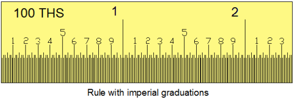
A typical rule may have 1/50" graduations on one edge and 1 /100“graduations on the other edge. As the inch is divided into 10 equal parts, each graduation is 1 /10" or 100/1000" (one hundred thousandths of an inch).
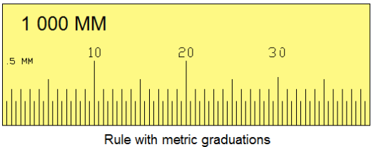
b) Metric graduations:
Many products are made in metric dimensions and require workers to be able to use a metric rule.
The typical metric rule has millimeter (mm) and half-millimeter graduations. Meters are typically divided into centimeters (1 /100 meter) and millimeters (1 /1000 m).
All metric measures are expressed in mm. Thus 1.0 meters (m) would be 1000 mm.
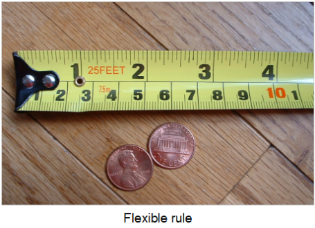
1.2. Reading a rule:
The first step in reading a rule is to know the value of the graduations on the rule. A careful study of the rule prior to taking measurements will make it possible for the technician to read the measurements quickly and accurately.
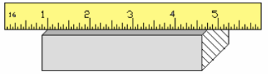
a) Incorrect measurement:
To get the full accuracy out of a rule, it is important to use it correctly. Never use the end of the rule to align with the edge of the work for a measurement.
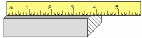
The end of a rule is often rounded off from misuse, and a true measurement will not be made.
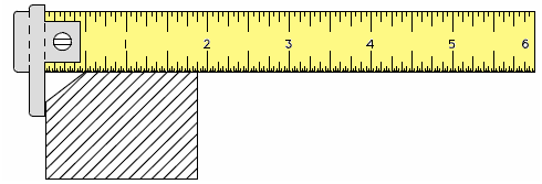
b) Correct measurement:
To obtain accurate measurements with a rule, the readings should be taken very carefully, and the rule should be kept in good condition.
To offset this, use an inch graduation as a reference point on the rule. Precision and reliable measurements are possible this way. With the graduation directly on the edge of the work and by not using the end of the rule, wear is inconsequential.
To offset this, use an inch graduation as a reference point on the rule. Precision and reliable measurements are possible this way. With the graduation directly on the edge of the work and by not using the end of the rule, wear is inconsequential.
c) Hook rules:
Steel rules may be purchased with a moveable bar or hook on the zero end which serves in the place of a butt plate. These rulers may be used to measure around rounded, chamfered or bevelled part corners.
The hook attachment becomes relied upon as a fixed reference. However, by its inherent design, it may loosen or become worn.
These convenient hook rules permit accurate measurements, even when the user cannot see if the rule is aligned with the measuring edge,.
This is especially useful for measuring from round corners, through hubs, for setting inside callipers, etc. The single hook is hardened and may be reversed or removed by a slight turn of an eccentric stud.
2. CALLIPERS:
2.1. Basic callipers:
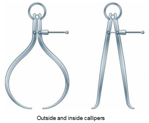
In some cases it possible or convenient to take measurements with a rule, such as when measuring inside and outside diameters or the width of a slot. A calliper can be used for these measurements.
A basic Lupercalia has two parts that can be moved in relation to one another, allowing different dimensions to be set. There are many types of callipers. Figure below shows two spring callipers commonly used for inside or outside measurement.
The distance between the ends of the legs are adjusted with a screw working against a spring. The callipers shown require the use of a rule or other direct reading device to determine the units of measurement.
Callipers can be used as a gauge when machining a part to size by first setting the calliper, with the aid of a rule, to the desired dimension and then comparing it to the part as work progresses.
Measurements:
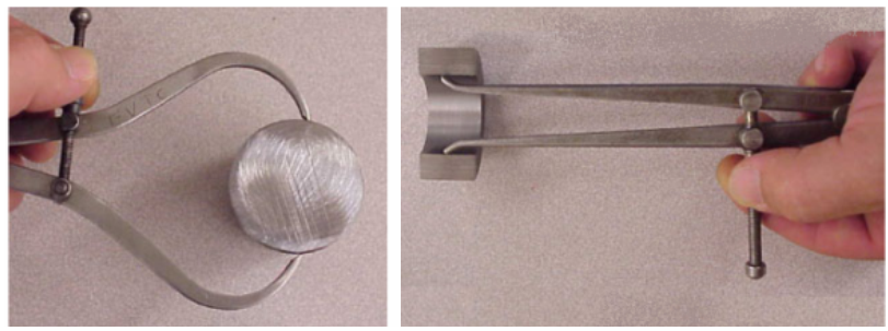
Callipers are used to measure features of a part that cannot be directly measured with a scale or micrometer measuring device. Of the two types mentioned, the inside calliper can be used to the greatest advantage.
The important thing to develop is a sensitive "feel" of the calliper and workpiece. Always take a measurement at least twice to see that it is reliable.
2.2. The vernier calliper:
Figure shows a vernier calliper. This device has a scale located on a beam with one fixed jaw. A second jaw is free to move up and down the beam. The ends of the jaws are formed so that either inside or outside measurement can be made.
The sliding jaws have two reference lines marked in and out. The distance between the jaws will be the value on the scale opposite the appropriate reference line.
If you look at the slide gauge, you will see two different scales. The large main scale runs over the whole length of the calliper and under this main scale a second scale which is shorter and called vernier scale. To define a value on the main scale is easy.
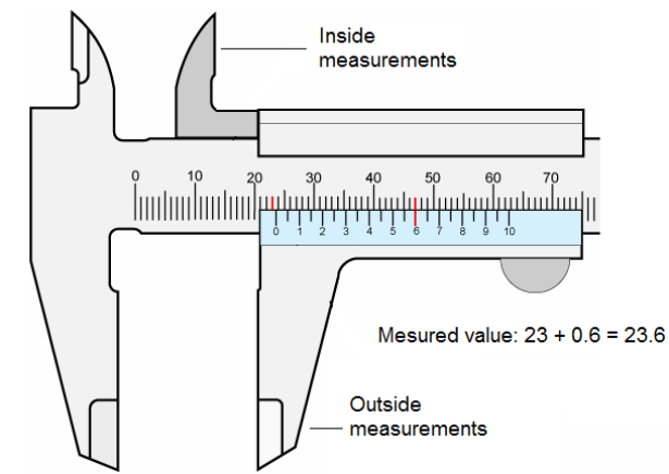
You just take the value opposing the value 0 of the vernier scale. In our present example this is 23 mm and some very small split portion of a millimeter.
To find out this value you have to find the value on the vernier scale - exactly opposing the gauge mark for a mm on the main scale. This value – in our example here 6 – is the value figuring behind the dot. It is 0.6 mm referring to a 1/10 vernier scale and has to be added to the mm value you just found on the main scale.
So the result is 23 mm plus 0.6 mm = 23.6 mm.
Note - Vernier scale length:
The gauge marks on the main scale and the gauge marks on the vernier scale are related in a defined ratio to each other; in our example here it is a ratio of 9:10. This means that the distance between two marks on the vernier scale is 0.9 mm and on the main scale it is 1 mm.
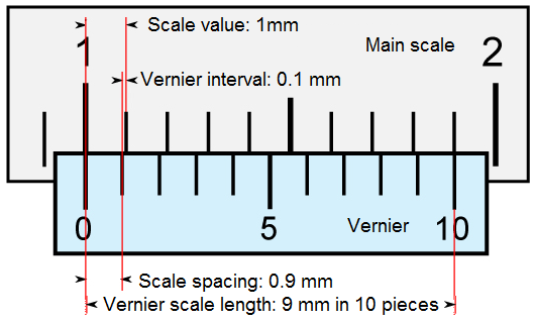
So it is made sure that the sum of the measuring is a value combined of measuring and adding the value shown on the vernier scale as a multiplicator of 1.
When there is a fraction of 0.1 mm the 1 appears on the vernier scale (i.e. 0.1 measured value + 0.9 mm is a distance between two gauge marks on the vernier scale).
Referring to a fraction of 0.3 mm i.e. a measured value of 0.3 mm + 3 times 0.9 (0.27 mm) the sum 3 will be shown on the vernier scale.
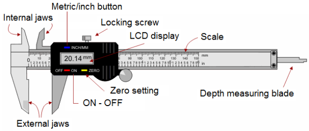
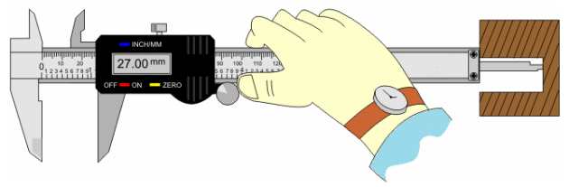
2.3. The digital vernier calliper:
The Digital Calliper (sometimes incorrectly called the Digital Vernier Calliper) is a precision instrument that can be used to measure internal and external distances extremely accurately.
The example shown below is a digital calliper as the distances/measurements, are read from a LCD display. The most important parts have been labelled.
Earlier versions of this type of measuring instrument had to be read by looking carefully at the imperial or metric scale and there was a need for very good eyesight in order to read the small sliding scale.
Manually operated vernier callipers can still be bought and remain popular because they are much cheaper than the digital version. Also, the digital version requires a small battery whereas the manual version does not need any power source.
Digital callipers are easier to use as the measurement is clearly displayed and also, by pressing the inch/mm button the distance can be read as metric or imperial.
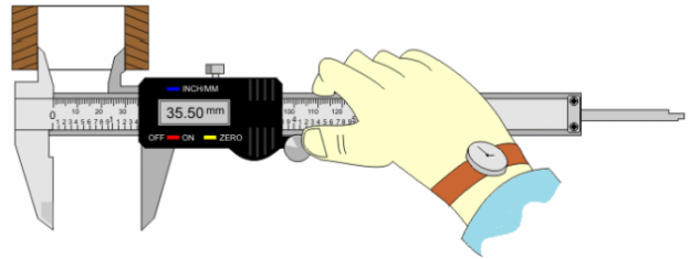
Here, the digital vernier calliper is used to measure the internal diameter of a piece of copper tube. the internal jaws are adjusted carefully until they touch the internal ‘sides'.
2.4. Outside micrometer measurement:
The micrometer is a device used to make small measurements.
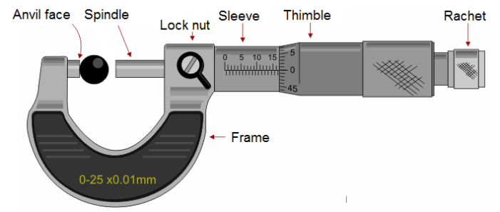
Micrometers consist of a basic C frame with the part measurement occurring between a fixed anvil and a moveable spindle. Measurement readings on a traditional micrometer are made at the barrel and thimble interface.
The term comes from micro plus meter, or one-millionth of a meter. In terms of English units, the basic micrometer is designed to accurately measure to one-thousandth of an inch.
The basic micrometer unit is made up of three parts, a hub, or barrel, a spindle and a thimble. Adding a C-shaped frame and an anvil completes the calliper. The anvil is attached by the frame to the hub. The primary scale is also on the hub. The spindle serves the same function as the sliding jaw on the slide calliper.
Although the basic micrometer mechanism is used on a number of different devices, the micrometer calliper is the most common.
Reading micrometers:
a) Imperial measures:
Read: 0.200” + 0.25” + 0.20” = 0.245”
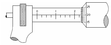
b) Metric measures:

Read: 18 mm + 0.5 mm + (10 x 0.01 mm) = 18.60 mm.
2.5. Inside micrometer measurement:
The inside micrometer is the most direct measuring tool used for inspection. The total length of the inside micrometer is itself the overall length being measured.
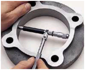
The inside micrometer is a much more accurate measuring tool for inside measurement than the calliper.
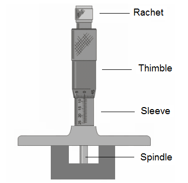
2.6. Depth micrometer measurement:
The depth micrometer is an accurate and reliable tool to use for depth measurement.
Remark:
Using a vernier calliper as a depth micrometer:
Measuring the depth of a hole can be very difficult. However, using a vernier calliper makes this task easy. The base of the vernier calliper rests on the top of the hole and the depth measuring blade is adjusted until it touches the bottom of the hole. The locking screw is tightened and the measurement can be read on the LCD display.
3. ANGLES MEASUREMENTS:
3.1. The plate protractor:
The simplest angle measuring device used in the machining industry is the plate protractor. The plate protractor is capable of measuring to within 1 degree.
The plate protractor is especially useful for layout.
A circle can be divided into 360 equal angles.
Each angle is called degree.
So a circle is 360 degrees. For calculation a degree is divided into 60 parts called minutes and a minute is sub-divided into 60 parts called seconds.
The plate protractor is especially useful for layout.
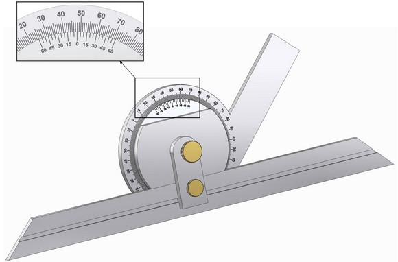
3.2. The bevel protractor:
The bevel protractor is used to establish and test angles to very close tolerances. It reads to 5 minutes or 1/20o and can be used completely through 360o.
The universal bevel protractor picks up where the blade protractor leaves off. The universal bevel protractor is designed for precision measuring and layout of angles.
The universal bevel protractor is capable of measuring to within 5 minutes or 1/12 of a degree.
The universal bevel protractor consists of a beam, graduated dial and blade which are connected to swivel plate (with vernier scale) by thumb nut and clamp.
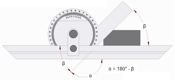
When the edges of the beam and blade are parallel, a small line on the swivel plate coincides with the zero line on the graduated dial, and when any measurement of an angle between the beam and the blade of 90 degrees or under is desired, the reading may be obtained direct from the position of the line on the swivel plate with regard to the graduation numbers on the dial.
But remember this: To obtain the measurement of the angle between the beam and the blade of over 90 degrees subtract the number of degrees as indicated on the dial from 180 degrees.
This is because the dial is graduated from opposite zero marks to 90 degrees each way.
The universal bevel protractor is capable of measuring obtuse angles as well as acute angles when accompanied with the correct attachments.
The main component of the bevel protractor is the main scale. The main scale is graduated into four 90-degree components. The main scale is numbered to read from 0 to 90 degree and then back from 90 degrees to 0.
Each space on the vernier scale is, therefore, one-twelfth of a degree.
One-twelfth of a degree is equal to 5 minutes.
To read the protractor, note where the zero on the vernier scale lines up with the degrees on the dial. The degrees are read directly from the main scale.
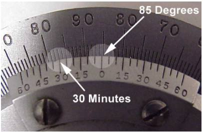
Add this number of 30 minutes read on the secondary scale. The total number of degrees and minutes would equal 85 degrees and 30 minutes.