OPERATION, FUNCTION AND USE OF ELECTRICAL GENERAL TEST EQUIPMENT
General-purpose test equipment covers the old-fashioned methods meant for avionic equipment testing. The electronic systems that equipped early aircrafts could be checked-out with general-purpose electronic test equipment (GPETE), such as multimeters, oscilloscopes, etc..
Due to the complexity of data bus transfer, general-purpose testing is rarely implemented on modern aircrafts.
However, when no automatic procedures can be carried out, general-purpose electronic test equipment and good troubleshooting procedures is used.
1. USING MULTIMETERS
1.1. What do multimeters measure?
A multimeter is a measuring instrument.
An ammeter measures current,
A voltmeter measures the potential difference (voltage) between two points, and
An ohmmeter measures resistance. A multimeter combines these functions and possibly some additional ones as well, into a single instrument.
1.2. Analog and digital multimeters:
Multimeters are designed and mass produced for electronics engineers.
Even the simplest and cheapest types may include features which you are not likely to use.
An analog multimeter moves a needle along a scale.
Digital meters give an output in numbers, usually on a liquid crystal display.
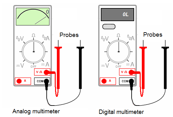
1.3. Making basic measurements with a multimeter.
The figures on the following pages show how to make basic measurements.
When connecting the test leads to the circuit or device, connect the common (COM) test lead before connecting the live lead; when removing the test leads, remove the live lead before removing the common test lead.
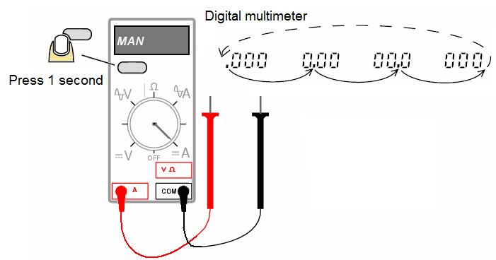
Manual range of multimeter:
Manual ranging is available in V AC, V DC, ohms, A AC, and A DC. To return to auto range, press for 1 second or change the measurement function.
a) Measuring resistances with an analog multimeter:
Before you attempt to measure resistance using an analog multimeter, you must determine the resistance range and set the multimeter (now an ohmmeter), in that range.
Now comes "zeroing" the ohmmeter to eliminate the ohmmeter's internal resistance and the lead resistance.
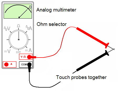
With the test lead tips touching each other, adjust the "zero" knob on the front panel so that the needle indicates a resistance of zero ohms (top scale).
Warning:
To avoid electric shock, injury, or damage to the Ohmmeter, disconnect circuit power and discharge all high-voltage capacitors before testing resistance, continuity, diodes, or capacitance.
Never use an ohmmeter in a circuit containing a voltage source.
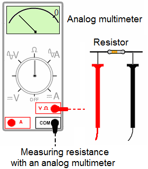
Experiment with different range switch positions and see which one gives you the best indication.
The best analog ohmmeter range gives a needle indication in the upper-third of the scale (top most scale).
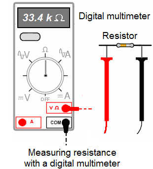
b) Measuring resistances with a digital multimeter:
While most digital meters are "auto-ranged“.
Some can be manually-ranged (over ride), and require appropriate range selection just as the analog meter.
Note:
In reading AC voltage or current, for the integrated RMS converter to correctly measure distorted waveforms, reading settling time increases to several seconds at the low end of AC voltage and current ranges. The Meter is not specified for use with current clamp accessories.
c) Measuring resistances using an ammeter and a voltmeter:
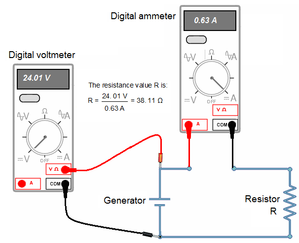
2. MEASURING A PRECISION RESISTANCE WITH AN AMMETER AND A VOLTMETER:
We have already seen that multimeter and ohmmeter are used to measure resistors. So, for a better precision it is useful to know how to measure resistors with ammeter and voltmeter. There are two possibilities to measure a resistor with an ammeter and a voltmeter:
short derivation circuit,
long derivation circuit.
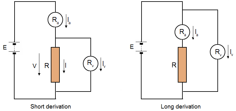
R: the unknown resistance,
E: voltage across the battery,
V: voltage across the resistor,
Ia: current passing through the ammeter,
Iv: current passing through the voltmeter,
Ra: internal resistance of the ammeter,
Rv: internal resistance of the voltmeter.
In accordance with Ohm's law, the value of the resistance is equal to: ![]()
The following study will teach you the best way to measure resistances.
a) Short derivation circuit:
The value of the resistance is: ![]()
The apparent value of the resistance is: 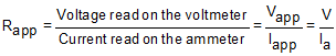
What is the relation between the real value R of the resistor and the apparent value ![]() ?
?
![]()
![]()
If we assimilate the apparent value ![]() at the real value R, the relative systematic error is the ratio between the apparent resistance minus the real resistance (
at the real value R, the relative systematic error is the ratio between the apparent resistance minus the real resistance (![]() - R) and the apparent resistance
- R) and the apparent resistance ![]() expressed as a percentage:
expressed as a percentage: ![]()
Hence:![]() .
.
Systematic errors are biases in measurement which lead to measured values being systematically too high or too low. Here the measurement is systematically too low.
Conclusion:
In a short derivation circuit, the relative systematic error between the apparent value of the resistance and this real value is lower when:
The internal resistance of the voltmeter is high.
The measured resistance is low.
the relative systematic error doesn't depend on the resistance of the ammeter.
The precision is better if the value of the unknown resistance is low.
b) Long derivation circuit:
The value of the r resistance is: ![]()
The apparent value of the resistance is: 
So, ![]()
If we assimilate the apparent value ![]() at the real value R, the relative systematic error is done by the formula:
at the real value R, the relative systematic error is done by the formula: ![]() .
.
Hence, ![]() ,
,
![]()
Systematic errors are biases in measurement which lead to measured values being systematically too high or too low. Here the measurement is systematically too high.
Conclusion:
In a long derivation circuit, the relative systematic error between the apparent value of the resistance and the real value is lower when:
The internal resistance of the voltmeter is low.
The measured resistance is high.
the relative systematic error doesn't depend on the resistance value of the voltmeter.
The precision is better if the value of the unknown resistance is high.
c) Summary
Voltmeters must have very high internal resistance.
Ammeter must have very low internal resistance.
In short derivation circuit the relative systematic error doesn't depend on the ammeter internal resistance.
In long derivation circuit the relative systematic error doesn't depend on the voltmeter internal resistance.
Use short derivation circuit to measure low resistances.
Use long derivation circuit to measure high resistances.
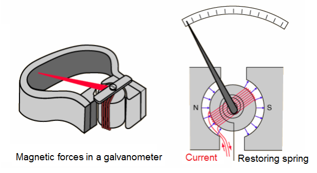
3. USING A GALVANOMETER TO MEASURE AN INTENSITY:
Galvanometer is the historical name given to a moving coil electric current detector.
When a current is passed through a coil in a magnetic field, the coil experiences a torque proportional to the current.
If the coil's movement is opposed by a coil spring, then the amount of deflection of a needle attached to the coil may be proportional to the current passing through the coil. Such "meter movements" were at the heart of the moving coil meters such as voltmeters and ammeters until they were largely replaced with solid state meters.
The accuracy of moving coil meters is dependent upon having a uniform and constant magnetic field.
The galvanometer consists of a coil of wire often rectangular, carrying the current to be measured.
There are generally many turns in the coil to increase its sensitivity. The coil is placed in a magnetic field such that the lines of B remain nearly parallel to the plane of wire as it turns. This is achieved by having a soft iron cylinder placed at the center of the coil. Magnetic field lines tend to pass through the iron cylinder, producing the field configuration.
The moving coil is hung from a spring which winds up as the coil rotates; this winding up produces a restoring torque proportional to the winding up (or twisting) of the spring, i.e. to the angular deflection of the coil.
The coil comes to equilibrium when this restoring torque k balances the torque due to the magnetic field balances the torque due to the magnetic field. Since by design field lines are radial,
The illustration shows one configuration of permanent magnet which was widely used in such meters.
We have sin θ ~ 1, so that for equilibrium: ![]()
Where:![]() . Thus the deflection of the galvanometer is proportional to the electric current I passing through it.
. Thus the deflection of the galvanometer is proportional to the electric current I passing through it.
4. USING AN OSCILLOSCOPE TO MEASURE VOLTAGE ON AC CIRCUITS:
a) Resistor (R) circuit:
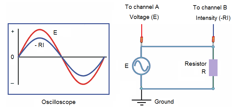
Note:
The phase shift between the voltage and the intensity is 0.
b) Resistor and capacitor (RC) circuit:
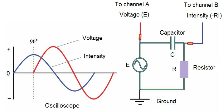
Note:
In this experiment the phase shift between the voltage and the intensity is near of 90°. So R << 1/Cω.
c) Resistor and inductor (RL) circuit:
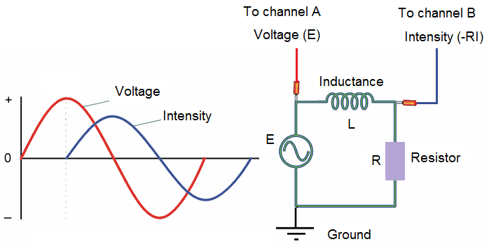
Note:
In this experiment the phase shift between the intensity and the voltage is near of 90°. So R << Lω.
5. USING POTENTIOMETERS AND RHEOSTATS:
5.1. Potentiometers and rheostats types:
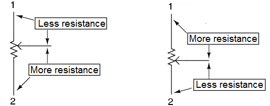
The wiper contact is the left-facing arrow symbol drawn in the middle of the vertical resistor element. As it is moved up, it contacts the resistive strip closer to terminal 1 and further away from terminal 2, lowering resistance to terminal 1 and raising resistance to terminal 2.
As it is moved down, the opposite effect results. The resistance as measured between terminals 1 and 2 is constant for any wiper position.
Here are illustrations of two potentiometer types, rotary and linear:
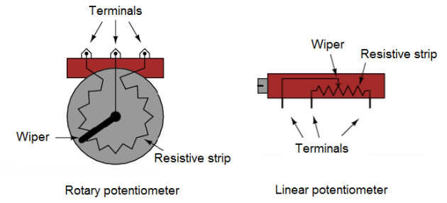
Some linear potentiometers are actuated by straight-line motion of a lever or slide button.
Others, like the one depicted in the previous illustration, are actuated by a turn-screw for fine adjustment ability.
The latter units are sometimes referred to as trimpots, because they work well for applications requiring a variable resistance to be "trimmed" to some precise value.
It should be noted that not all linear potentiometers have the same terminal assignments as shown in this illustration. With some, the wiper terminal is in the middle, between the two end terminals.
5.2. Potentiometer operation and use:
Just like the fixed voltage divider, the potentiometer's voltage division ratio is strictly a function of resistance and not of the magnitude of applied voltage.
In other words, if the potentiometer knob or lever is moved to the 50 percent (exact center) position, the voltage dropped between wiper and either outside terminal would be exactly 1/2 of the applied voltage, no matter what that voltage happens to be, or what the end-to-end resistance of the potentiometer is.
In other words, a potentiometer functions as a variable voltage divider where the voltage division ratio is set by wiper position.
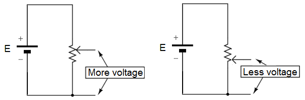
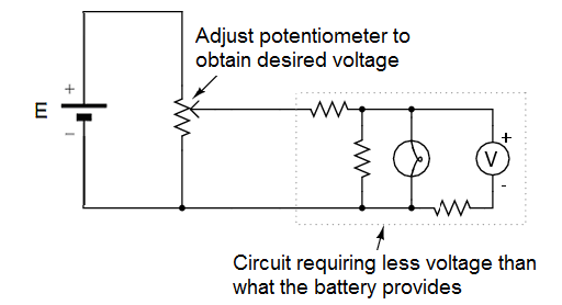
This application of the potentiometer is a very useful means of obtaining a variable voltage from a fixed-voltage source such as a battery.
If a circuit you're building requires a certain amount of voltage that is less than the value of an available battery's voltage, you may connect the outer terminals of a potentiometer across that battery and "dial up" whatever voltage you need between the potentiometer wiper and one of the outer terminals for use in your circuit.
When used in this manner, the name potentiometer makes perfect sense: they meter (control) the potential (voltage) applied across them by creating a variable voltage-divider ratio. This use of the three-terminal potentiometer as a variable voltage divider is very popular in circuit design.
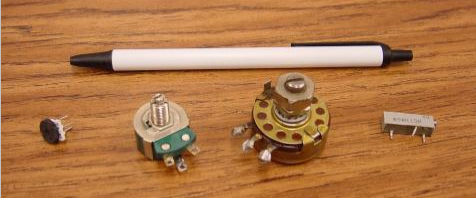
Shown here are several small potentiometers of the kind commonly used in consumer electronic equipment and by hobbyists and students in constructing circuits:
The smaller units on the very left and very right are designed to plug into a solderless breadboard or be soldered into a printed circuit board. The middle units are designed to be mounted on a flat panel with wires soldered to each of the three terminals.
The following photograph shows a real, rotary potentiometer with exposed wiper and slidewire for easy viewing. The shaft which moves the wiper has been turned almost fully clockwise so that the wiper is nearly touching the left terminal end of the slidewire:
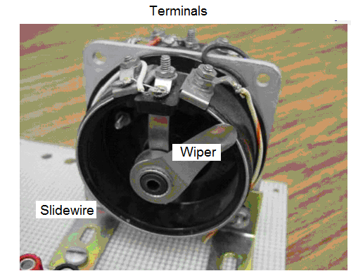
Here is the same potentiometer with the wiper shaft moved almost to the full-counterclockwise position, so that the wiper is near the other extreme end of travel:
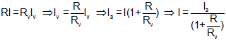
6. OPERATION OF WHEATSTONE BRIDGE:
The accuracy of resistance measurements by the multimeter method is limited, mainly because of the relative accuracy of the meters. In this lesson, we will study the Wheatstone bridge which is used where precise resistance measurement are required.
The figure below shows the circuit diagram of the Wheatstone bridge.
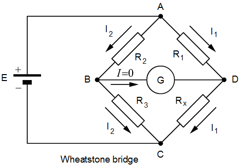
The galvanometer (G) is an instrument used for measuring a small electric current. It is connected as shown.
Resistances R1, R2 and R3 are known values, and RX is the resistance to be measured.
In most bridges, R1 and R2 are adjustable in ratios of 1/1, 1/10, , 1/100, etc., and R3 is adjustable in small steps. In measuring a resistance, is adjusted until the galvanometer reads zero. In this condition, the bridge is said to be balanced.
Since the galvanometer reads zero, it is evident that the points B and D have exactly the same potential; that is, the voltage drop from A to B is the same as from A to D.
Expressed as an equation:
VAD = VAB , so R1I1 = R2I2 ............(1)
Similarly, the voltage drop across RX must be equal to that across R3; hence:
RXI1 = R3I2 ............(2)
Dividing equation (2) by equation (1): ![]() ....... (3)
....... (3)
Equation (3) is the fundamental equation of the Wheatstone bridge. By solving this equation for the only unknown, RX , the value of the resistance under measurement can be computed.
Since the equilibrium conditions of the bridge are not directly related to the voltage of the source, we may be tempted to think that the value of the voltage is not important.
In practice, however, the resistors used in Wheatstone bridges are very precise, and they are usually delicate. We must make sure that their power-dissipating capabilities are not exceeded by applying too high a voltage.