LUBRICATION EQUIPMENT AND METHODS
The basic functions of a lubricant are friction reduction, heat removal and suspension of contaminants.
Designing a lubricant to perform these functions is a complex task, involving a careful balance of properties both in the base oil and the performance enhancing additives.
Simply stated, friction is reduced by maintaining a film of lubricant between surfaces that are moving with respect to each other, thereby preventing the surfaces from coming into contact and subsequently causing surface damage.
Friction is a common element in daily life. One can walk up a steep ramp without slipping back because of high friction between shoe soles and the ramp surface. One can slide down a ski run because friction between packed snow and skis is low. Lubrication is of two general types based on the operating environment; that is, load and speed of the equipment and viscosity of the lubricant. Smooth surfaces separated by a layer of lubricant do not come into contact and, hence, do not contribute to frictional forces.
This condition is called hydrodynamic lubrication.
Boundary lubrication, on the other hand, arises when there is intermittent contact between surfaces, resulting in significant frictional forces.
1. HYDRODYNAMIC LUBRICATION:
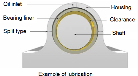
Keeping a liquid film intact between surfaces moving with respect to each other is generally done mechanically, as by pumping. In a cylindrical journal and bearing, the rotary shaft acts as a pump to maintain the lubricant film. The journal floats on a film of oil with an equilibrium thickness established between oil input and oil leakage (mostly at the bearing ends).
The equilibrium thickness of the oil film can be altered by:
Increasing load, this squeezes out oil.
Increasing temperature, causing more oil leakage.
Changing to lower viscosity oil, which also causes more oil leakage.
Reducing journal speed, which generates a thinner oil film.
Lubrication of a shaft rotating in a cylindrical bearing offers the classic example of the hydrodynamic theory of bearing friction, as described by Osborne Reynolds in 1886. The theory assumes that under these conditions, friction occurs only within the fluid film, and is a function of fluid viscosity.
Load has little effect on film thickness because at the pressures involved, the oil film is actually more rigid than the metal surfaces. Therefore, the main effect of a load increase is to deform the metal surfaces and increase the contact area, rather than decrease the film thickness.
The equilibrium thickness of the oil film can be altered by:
Increasing load, which squeezes out oil.
Increasing temperature, causing more oil leakage.
Changing to lower viscosity oil, which also causes more oil leakage.
Reducing journal speed, which generates a thinner oil film.
1.1. Boundary lubrication:
The simple assumptions made in discussing fluid film lubrication are hardly ever valid in practice. Under certain conditions such as shock loading, steady heavy load, high temperature, slow speed, and critically low viscosity, the lubricant system no longer remains in the hydrodynamic regime.
A situation arises wherein there is intermittent contact between the surfaces, resulting in a significant rise in temperature and subsequent destruction of the contacting surfaces.
Under these circumstances, the fluid film is no longer capable of adequately protecting the surfaces, and other approaches must be employed such as adding film-forming additives.
1.2. Lubricant viscosity:
Viscosity is one of the most important properties of a lubricating oil. It is one factor responsible for the formation of lubricating films under both thick and thin film conditions. Viscosity affects heat generation in bearings, cylinders and gears due to internal fluid friction. It affects the sealing properties of oils and the rate of oil consumption. It determines the ease with which machines can be started at various temperatures, particularly cold temperatures. The satisfactory operation of any given piece of equipment depends on using an oil with the proper viscosity at the expected operating conditions.
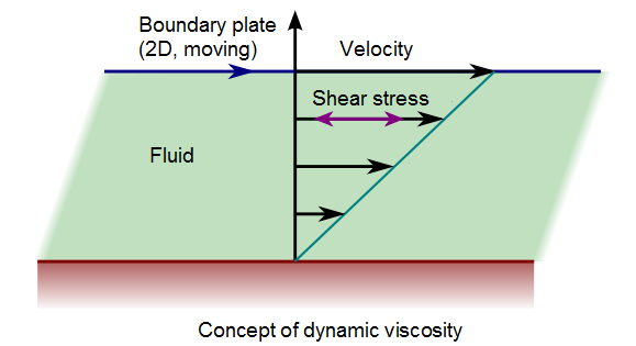
The basic concept of viscosity is shown in the figure, where a plate is being drawn at uniform speed over a film of oil. The oil adheres to both the moving and stationary surfaces.
1.2. Lubricant specifications:
We have included a table of commercial and military lubricants and their recommended uses.
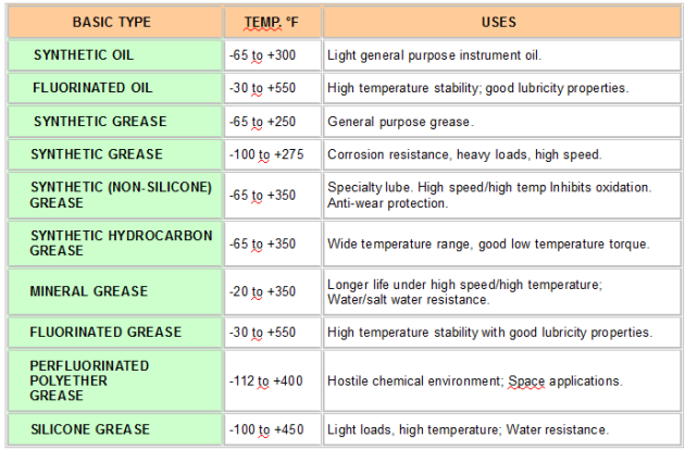
Example: For ball bearings this uses are ordered without a specified lubricant to lubricate with MIL-L-6085 oil.
The standard quantity of oil varies with bearing size, but is approximately one drop (3–6mg) per bearing up to R-2 size and two drops (6–12mg) for larger sizes.
The standard quantity of grease is 30% (±5%) of the bearing's internal free volume.
2. INDUSTRIAL APPLICATIONS:
2.1. Concrete form oils:
Concrete form oils are lubricants which are formulated to provide a clean, quick release of the plywood, metal, or plastic forms from concrete after setting. They are usually available in a light viscosity to accommodate spraying of the lubricant on the forms.
2.2. Cutting oils:
The main functions of cutting oil are to lubricate or reduce friction between the tool and the work piece, and to act as a coolant by rapidly removing heat generated at the tool / work piece interface.
Soluble cutting oils are mixed with water in proportions of 3 to10%. They are used where rapid heat removal is a major requirement. They are usually formulated with emulsifiers, rust inhibitors, and EP additives.
Insoluble cutting oils are used in operations involving tough cutting such as tapping, threading, and broaching. Lubricity and anti-weld characteristics are important characteristics of this cutting oil.
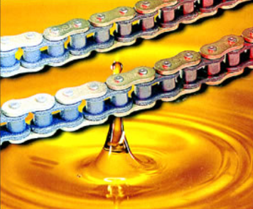
2.3. Chain oils:
These oils are formulated to lubricate saw chains, and should provide the following benefits:
An unbroken film of lubricant between chain links and bars.
Anti-wear characteristics to prevent chain and bar wear.
Chain oil should have throw-off resistance. Classified as "tacky".
Prevent corrosion of the chain.
2.4. Compressor oils:
These oils are formulated for use in reciprocating and rotary air compressors. They are available in different viscosity grades for use in different ambient temperature ranges.
2.5. Heat transfer fluids:
A lubricant used as a heat transfer medium in applications such as:
Plastic extrusion machines.
Textile dryers.
Die casting.
Some high quality heat transfer fluids can provide clean, odorless operation up to temperatures of 326°C. These are usually semi-synthetic heat transfer fluid.
2.6. Hydraulic oil:
Hydraulic systems provide a means to transfer power where gears are impractical. A typical system includes a reservoir for the hydraulic fluid, a pump, transfer hoses, and return hoses to the reservoir.
The important characteristics of a hydraulic fluid are:
Thermal stability;
Corrosion protection;
Anti-wear properties;
Anti-foaming properties.
The oil is available in different viscosity grades to accommodate a variety of ambient operating temperatures.
2.6. Industrial gear lubricants:
These oils provide protection to different types of industrial gears which are often operated under high contact pressures, and intermittent shock-loading. Gear lubricants often contain an EP (Extreme Pressure) Additive.
A wide variety of ISO viscosity grades are available from your supplier.
2.7. Refrigeration lubricant:
This lubricant is used in commercial refrigeration compressor systems. This oil is available in two formulations:
For use in CFC (chlorinated fluorocarbon) systems.
For use in ammonia refrigeration systems.
3. INDUSTRIAL METHODS:
3.1. Oil bath lubrication:
Oil bath lubrication is widely used for low or medium speeds. The oil level should be at the center of the lowest rolling element.
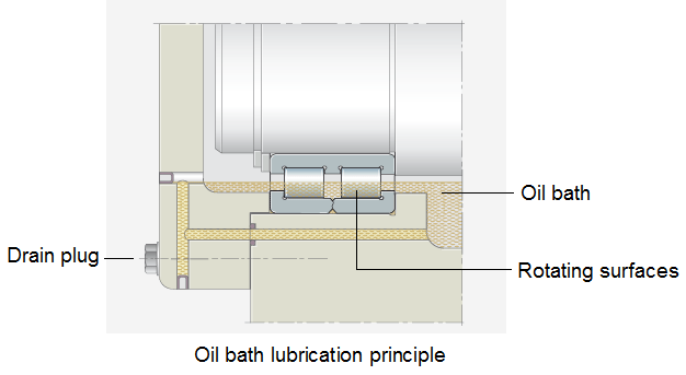
It is desirable to provide a sight gauge so the proper oil level may be maintained.
3.2. Drip feed lubrication:
Drip feed lubrication is widely used for small ball bearings operated at relatively high speeds. The oil is stored in a visible oiling apparatus.
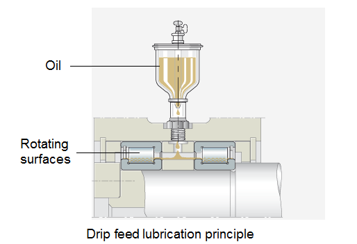
The oil drip rate is controlled by a screw on the top of the apparatus.
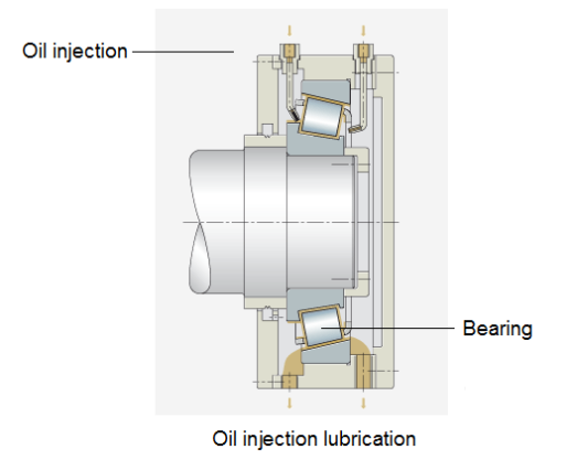
3.3. Oil injection lubrication:
In bearings running at high speeds, the oil is injected into the gap between the cage and bearing ring, Injection lubrication using large recirculation quantities is associated with high power loss.
Heating of the bearings can only be held within limits with a considerable amount of effort.
3.4. Circulating lubrication:
Circulating lubrication is commonly used for high-speed operation requiring bearing cooling, and for bearings used in high temperatures.
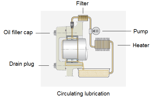
As shown in figure oil is supplied by the pipe on the right side, travels through the bearing, and drains out through the pipe on the left.
After being cooled in a reservoir, it returns to the bearing through a pump and filter.
The oil discharge pipe should be larger than the supply pipe so an excessive amount of oil will not back up in the housing.