RELATIONSHIP BETWEEN LIFT, WEIGHT, THRUST AND DRAG
When an aircraft is on the ground, its weight exerts a pressure on its landing gears. To make it possible for an aircraft to lift itself and move in flight, it is necessary to overcome the force of gravity and to create at least a force allowing displacement. In the previous chapters lift (L) and drag (D) were developed for an aircraft in an equilibrium position. During flight various forces act on the aircraft and they influence the reactions of some of the other forces.
1. AXES OF THE AIRCRAFT:
1.1. The three axes of an aircraft:
The aircraft is a solid reference mark which cannot be changed. A reference mark passing through the centre of gravity of the aircraft is generally used. But the centre of gravity can move during flight (due to emptying of the fuel tank, dropping, etc.).
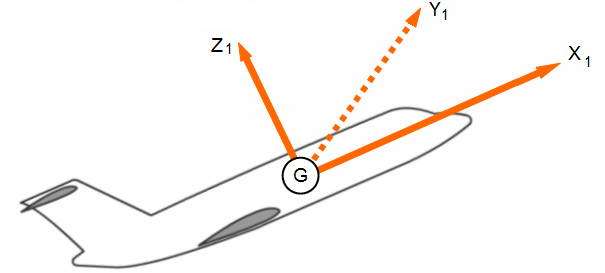
Axis GX1: parallel to the longitudinal axis and in the symmetry plane.
Axis GZ1: perpendicular to axis GX1 and in the symmetry plane.
Axis GY1: perpendicular to the plane (Z1; G; X1).
1.2. The three axes related to speed (Aerodynamic axes):
Its point of application is generally the same as the one for the three axes of the aircraft.
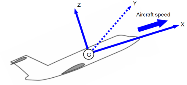
Axis GX: parallel to the speed V and in the symmetry plane.
Axis GZ perpendicular to GX and in the symmetry plane.
Axis GY perpendicular to the plane (Z; G; X).
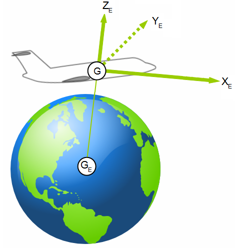
1.3. The axis related to the earth:
As the aircraft is flying through the air, we take a reference mark in the environment.
Horizontal axis: GXE.
Vertical axis: GZE (direction of the centre of the earth)
Axis GYE perpendicular to the plane (ZE; G; XE).
1.4. Various angles:
When considering an aircraft, several angles come into play. By considering the fuselage and the wing to be one element, the angle of attack of the aircraft is equal to the angle of attack of the aerofoil.
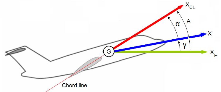
A: attitude angle.
XGXE: angle of slope.
XCLGX: angle of attack.
A = XGXE + XCLGX
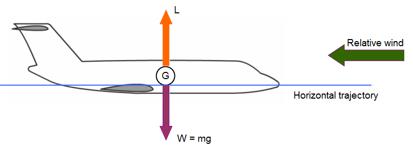
2. RELATIONSHIP BETWEEN WEIGHT AND LIFT:
Always perpendicular to the direction of the relative wind (V), the lift opposes the weight of the aircraft. The lift depends directly on the density of air (ρZ), the speed of the aircraft (velocity of the relative wind) and of its surface area (S). The lift depends on another parameter called coefficient of lift noted CL which characterizes the angle of attack, the shape and the surface quality of the wing.
Mathematically, lift (in N) is written:
![]()
At equilibrium (horizontal trajectory):
![]()
An aircraft in flight will have different reactions according to the relation between the force due to the weight and the lift.
When the two forces are of the same magnitude but act in opposite directions, the aircraft is in an equilibrium position at a fixed altitude. If one of the two forces changes, the aircraft is no more in equilibrium and its altitude will change. If lift decreases, the aircraft loses altitude and if lift increases the aircraft gains altitude.
3. RELATIONSHIP BETWEEN TRUST AND DRAG:
To have a displacement of the aircraft, thrust must be created. From the very beginning of displacement (even on the ground) a force of resistance, due to the air (and friction on the ground), will be present, this force is known as drag.
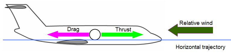
The greater the thrust, the more significant the drag will be.
Thus drag will act on the aerodynamic resultant and consequently on lift; thrust will allow a displacement of the aircraft and therefore a gain in speed.
Always parallel to the relative wind (V), drag will oppose the pulling force of the propellers engines or the thrust of the turbine engines.
The drag will depend on the same parameters that we defined previously for lift except that only the last parameter evoked in the formula will bear the name of coefficient of drag and will be denoted (CD).
Mathematically, the drag is written:
![]()
At equilibrium (horizontal flight and constant velocity):
![]()
4. RELATIONSHIP BETWEEN DRAG AND LIFT:
The aerodynamic resultant is the sum of the forces acting on an aerofoil placed in a flow. When the aerodynamic resultant is broken down into 2 components, 2 forces are obtained, drag and lift.
Drag is always parallel to the relative wind and opposes the forward movement of the aircraft.
Lift is always perpendicular to the relative wind and opposes the weight of the aircraft.
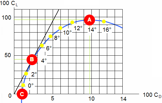
An action on one of the two forces will modify the aerodynamic resultant and consequently affect the other force. The study of polar curve shows the relation between lift and drag for a given angle of attack.
Conclusion:
With the angle of attack equal to zero, the weight, the drag, the lift and the thrust are in direct relation. An action on one of these forces will cause a change in the other forces.
However, the angle of attack of an aircraft is never zero, the center of pressure and its centre of gravity are rarely at the same point. In the relationship between the forces, the angles must be taken into account for calculations.
In the following chapters on stabilized flights we will develop the flight equations by taking into account the various points at which the forces act.
5. RELATIONSHIP BETWEEN LIFT AND DRAG:
![]()
The polar curve:
Let us summarize the aerodynamic performances of a wing that will depend on the following characteristics:
an optimal aerodynamic efficiency equivalent to a good aerodynamic output.
the largest value of L since it is L which will increase.
the smallest possible value of D, which characterises resistance to motion.
the angle of attack, defined by the aerofoil of the wing subjected to the direction of the relative wind.
These four characteristics can be found on the polar curve.