INFLUENCE OF LOAD FACTOR: STALL, FLIGHT ENVELOPE AND STRUCTURAL LIMITATIONS
The study of the various forces applied on an aircraft moving in the atmosphere is called the mechanics of flight. Any plane, when designed, is equipped with a clean structure adapted to the forces which act on it.
Below: Testing the structure of an aircraft

These forces are classified in 3 categories:
Mass forces: They are related to the mass of the plane. They include the weight, the inertias and centrifugal forces.
Aerodynamic loads including lift and drag.
Propulsion forces corresponding to thrust and torque of the engines.
1. THE LOAD FACTOR:
The load factor is sometimes expressed as a ratio of “g”. The load factor has no dimension.
It is the value which can be observed on the accelerometers with a “g” scale. These indicators inform us on the value of the linear acceleration which the aircraft undergoes (in m/s 2). The accelerometer indicates the value of the acceleration: positive and negative.
This value of “g” is different from the acceleration of terrestrial gravity which bears the same unit (about 9, 81 m/s 2 in Paris).
The load factor represents for the pilot as well as for the aircraft, the number of times it is subjected to its own weight during an operation.
The accelerometer, as its name implies measures and stores the significant load factor and accelerations for the monitoring of the process of the airframe.
Consider the case of a straight and level flight, in the presence of the following forces: thrust T will be opposed by Drag D, the lift L will be opposed by the weight W of the aircraft.
1.1. Flight without acceleration:
The calculation of weight reveals a first expression of "g ". In the formula W = Mg, the value of "g" corresponds to the acceleration of terrestrial gravity and will not in any case act on the value of the load factor.
Without any inertia, the apparent weight will be equal to the actual weight and the load factor will be equal to 1.

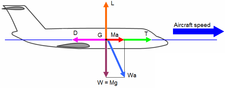
1.2. Flight with a constant positive linear acceleration:
Thrust T will be opposed by Drag D, the lift L will be opposed by the weight W of the aircraft.
T = D + Ma, where “a” is the linear acceleration,
L = W = Mg
![]()
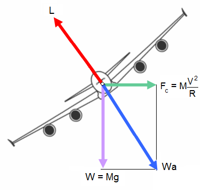
1.3. Flight with a constant positive circular acceleration:
We observed in the general information that a level turn without acceleration gives rise to a centrifugal force Fc. This force Fc, is added to the weight and the sum of these two forces represents the apparent weight of the aircraft.
![]()
The lift L is thus opposed by the apparent weight and in order not to lose altitude with an increase in weight it is necessary to increase the lift. ![]()
![]()
It will thus be significant to define for each type of aircraft a stalling speed according to the evolution of the load factor. By observing the flight envelope, it can be seen that a specific aerofoil is considered.
This form is quite simple due to the representation of the stalling curves defined by the flight envelope.
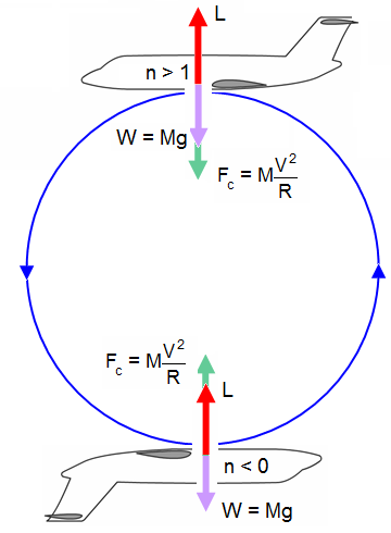
1.4. The sign of the load factor:
Let us observe an aircraft carrying out a loop. The centrifugal force is directed in the direction of the centre of loop. The value of the centrifugal force is higher than the value of the weight.
At the highest point of the loop, the aircraft is in a normal flight configuration. The weight and the centrifugal force are vertically directed and in the same direction. The load factor n is > 1.
Let us observe this aircraft at the same place in the loop, but this time is in inverted flight. The weight and the centrifugal force are vertically directed but in opposite directions.

2. LOAD FACTOR AND THE AIRFRAME:
An aircraft is composed of a structure and other components.
The structure is the resistant unit forming the external shape of the plane and which supports the forces resulting from the equilibrium between:
Aerodynamic forces,
Weight,
Thrust,
Pressure.
The study and the complete definition of a structure comprise several aspects, whose principal ones are:
The materials being used,
The design of the structure,
Dimensioning.
As we explained in the previous chapters, the regulation imposes for each type of aircraft an acceptable maximum load factor.
Beyond the results obtained, from the checks carried out on the resistance of the structure, the limitation of the maximum load factor will influence other parameters:
Examples:
The maximum rudder deflection thus defining their efficiency.
The maximum forces of the servos actuating these same control surfaces at the time of maneuver.
The downward slope of a trajectory will be also limited, in order to place the aircraft at an acceptable height.
The statements of the accelerometer make it possible to follow the ageing process of the structure. In the event of exceeding the maximum load factor, it will be necessary to carry out a thorough inspection of the airframe in order to detect any possible deformations or appearances of cracks.
2.1. Flight loads apply on the structure:
Various loads:
During its life span, the structure of an aircraft experiences:
Aerodynamic forces due to the distributions of the pressures on external surfaces,
Loads of inertia due to gravity, internal and external accelerations including vibrations,
Loads introduced by the undercarriages at the time of ground maneuvers,
Thrust,
Pressure loads in the pressurized fuselages, the tanks also undergo loads due to the shaking of the fuel,
Thermal loads which result from the differences in temperature occurring in the structure, they are also due to the kinetic heat at high speeds,
Various loads (lift, ground wind...).
We could think that the inspections of the structure of a plane require the study of the distribution of these loads in all ground or flight maneuvers.
In practice, these inspections are carried out for a limited number of maneuver cases, which we call calculation cases, which are the regulations worked out by the official services in various countries.
Regulations:
The regulations for a transport aircraft are of two types:
Some relate only to the delivery of the airworthiness certificate (AC) and ensure a minimum level of performance for the plane required by the AC. They are the regulations of construction and AC.
Others relate only to the exploitation and ensure a minimum level of safety during this exploitation. These are the regulations of exploitation
American regulations:
They are Federal Aviation Regulation (FAR) emanating from the Federal Aviation Administration (FAA) which is located in Washington. We can quote the FAR 23 and FAR 25 for civil aircrafts and MIL 886 for military aircrafts.
European regulations:
To recall, let us quote the regulation AIR 2051 taken from CAR4b and SR 422B. This regulation has been abandoned and replaced by the PART (EASA authorities) which is a European regulation.
2.2. Flight domains:
Various fields:
In the general information, we detailed the flight envelope D1 registered in the regulation. In order to observe the load factor rigorously various fields are exploited:
D1 field: symmetrical operation with or without pitch changes, the plane being in cruising or diving configuration: (Example: resource or stable turn).
The D2 field: asymmetrical operation in cruising configuration: (Example: roll).
The D3 field: maneuver with directed high-lift devices, undercarriages deployed or not
The D4 field: aircraft in uniform level flight in the cruising or diving configuration and flying in a symmetrical gust.
The D5 field: field of symmetrical gusts directed over high-lift devices, undercarriages deployed or not.
2.2. Description of the flight envelope:
The flight domain D1, also called flight envelope, was generally approached in a theoretical manner.
The paragraph which will follow will make it possible for us to go into detail on certain points.
Equivalent speed ES:
First of all let us define in detail the properties of the speed observed in the X-axis and denoted as ES for Equivalent Speed.
An equivalent speed is used to simplify calculations, it takes into account the variations of the density with the change in altitude.
From the density of the air:
 with
with ;
;The equivalent speed ES will be equal to:

Thus, for calculation purposes, one will be able to write:

According to the program they must follow, the planes are classified in three categories defined by the strongest value of the limiting load factor, here denoted "ni‘' and indicated in the technical specifications:
Category I: 2.5 <ni< 4
Category II: 4 <ni< 6
Category III: 6 <ni
Functions "n‘' (ES) are positive values of the load factor. To these positive values correspond the negative values of the load factor defined in the technical specifications by the law: Negative Load factor limits ("n‘') (ES) = - 0.4.
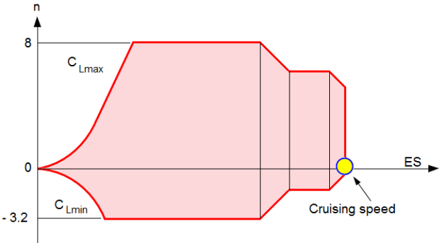
Let us observe the D1 field of a fighter aircraft following the standard AIR 2004 E and that of a transport aircraft following the standard FAR 25.
Flight envelope of the fighter AIR 2004 E:
We are in the presence of a flight envelope of category III.
The limiting load factors in this standard are determined by the physiological resistance of the pilot and that of the structural strength. If taking into account the minimum time, the maximum acceleration that a human can withstand is "8g" for a fighter pilot (equipped with a g-suit).
We will thus adopt for the fighters a positive limiting load factor equal to 8.
The extreme loads will have to resist a value of n = 12.
The resistance of the structure and that of the pilot are made homogeneous.
As far as a fighter plane is concerned, the performances of the aircraft are classified as confidential. The safety requirements are certainly not neglected but rather considered as of secondary importance.
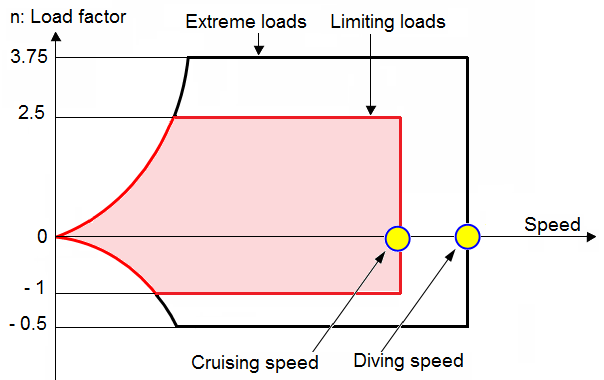
Flight envelope of an aircraft transport (Standard FAR 25):
For transport aircrafts, there are no sudden maneuvers.
The value of the positive limiting load factor is 2.5. It is a category 1. This parameter covers the avoidance maneuver which can prevent a collision.
The weight of the structure plays a significant role in the profitability of the plane.
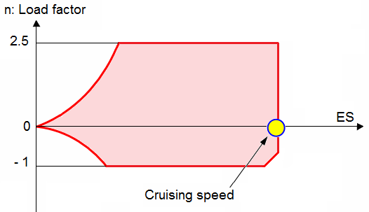
When designing an aircraft, we will have to keep the size of the structure small.