STEADY STATE FLIGHTS, PERFORMANCE
In the previous studies, the various forces on the aircraft were explained in detail. The required conditions for flight depend on two equations: the equation of lift and the equation of thrust. Now, we will discuss the various types of stable flight and the performances.
1. FORCES IN ACTION IN A STABLE FLIGHT:
At stable flight, the speed of the aircraft is constant.

Reference axis:
The lift axis is perpendicular to velocity.
The thrust axis is parallel to the velocity.
The drag is opposite to the thrust.
The weight is vertical.
Expression of the lift:
on the GX axis: 0,
on the GY axis: 0,
on the GZ axis: L.
Expression of the thrust:
on the GX axis: T,
on the GY axis: 0,
on the GZ axis: 0.
Expression of the drag:
on the GX axis: D,
on the GY axis: 0,
on the GZ axis: 0.
Expression of the weight:
on the GX axis: -MgsinY
on the GY axis: 0,
on the GZ axis: - MG cosY.
2. EQUILIBRIUM AT STABLE FLIGHT:
The equation of the equilibrium is:
![]()
At GX axis:
![]()
At GY axis:
0 = 0
At GZ axis:
![]()
2.1. Horizontal steady state flight:
The angle of slope is zero (horizontal flight) and the speed of the aircraft is constant,
![]()
For flight these two equations are important for the calculation of the weight of the aircraft. The weight is a function of the density of the air, the wing surface, the speed of aircraft and the coefficient of lift.
With the angle of slope equal to zero, the weight, the drag, the lift and the thrust are in direct relation. An action on one of these forces will cause a change in the other forces.
However, the center of pressure and its centre of gravity are rarely at the same point. In the relationship between the forces, the angles must be taken into account for calculations. In the following chapters on stabilized flights we will develop the flight equations by taking into account the various points at which the forces act.
2.1.1. Propeller planes:
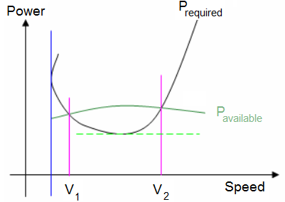
The flight of propeller planes is in the subsonic region. We use the power diagram; the polar curve does not depend on the Mach number. On the power diagram, the available power curve (P available) and the required power curve (P required) intersect at two different places. A level flight can be achieved at two different speeds. The flight at speed V1 is known as the first phase, the flight at speed V2 is known as the second phase.
Note: It happens that certain aircraft engines have certain characteristics without the second phase.
Effect of power:
From the power equation:

To obtain a safe flight, it is necessary to provide a minimum engine power. A flight with the minimum capacity is carried out at a higher speed than the minimum speed. A flight with the minimum engine power must be achieved with minimum drag. The polar curve gives an angle of attack which requires a faster speed. During the flight with minimum engine power, if speed increases, the plane slows down; we observe the same thing if speed decreases, the plane slows down.
By increasing the altitude, the engine output power decreases. This implies that when an aircraft flies at an altitude with maximum aerodynamic efficiency, it no longer flies at the maximum speed.
Effect of speed:
For a propeller plane, flight at high speed is carried out with CD almost constant. The power required is proportional to the cube of the speed, for an increase in speed the required power is then very significant.
For the flight at minimum speed, the value of CL is maximum, the required power is significant.
Effect of altitude:
Assuming that the engine power is kept constant, let us take the lift and power equations:

Consider an aircraft, with known weight mg, wing surface area S and which is maintained at a constant power.
If altitude increases, the density decreases. To balance the equations, the terms and are increased.
For an increase in altitude, it has to accelerate first. At the same time, the angle of attack increases, thus CL and CD increase. If the angle of attack increases, speed decreases. Therefore we have a variation in speed. It will increase then decrease.
We maintained the power constant by increasing altitude, the engine of the aircraft is less effective when flying at a certain altitude. It is possible to have a better aerodynamic efficiency at relative speeds as long as the engine power output does not decrease dramatically
Effect of weight:
Assume that altitude is constant and that the weight of the wing Mg/S is proportional to Mg.
Consider an aircraft with known weight mg and wing surface area S. During a level flight, the aircraft has an angle of attack which generally is higher than the minimum angle of attack.
For this aircraft, an increase in weight under the same flying conditions involves a loss of speed.
At low angles of attack, there is a small decrease in speed. On the other hand, for higher angles of attack, the decrease in speed is significant. In order to fly at the same angle of attack, with two different weights, the term ρV2 is proportional to Mg.
2.1.2. Jet aircraft:
The flight envelope of jets includes the incompressible and compressible medium. A jet in flight can travel at subsonic, then transonic and supersonic speeds. For a level flight, it is necessary to see the various regions. It is analyzed using the following figure.

Effect of thrust:
a ) Incompressible medium.
This flight envelope is also that of the propeller planes. They have the same characteristics.
The aircraft can fly at two different speeds. Straight and level flights are more easily achieved at the speed V2.
To ensure level flight, the engine must provide useful thrust higher than the minimum required thrust. The corresponding angle of attack is the angle at which maximum aerodynamic efficiency can be obtained.
b) Compressible medium.
This flight envelope is that where the planes fly at a Mach number higher than 0.7 . The aerodynamic characteristics are different, the analysis is carried out with the CD graph.
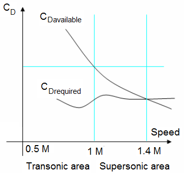
During a transonic flight:
Consider the graph of CD in transonic flight. The gradient of the CD curve changes rapidly before reaching the speed of Mach 1. The shape of the curve determines the Mach number of the level flight, there must be a great increae in thrust in order to change the speed.
During a supersonic flight:
In a level flight the speed of the aircraft is higher or equal to Mach 1. We use the CD graph in supersonic flights. The CD graph is less sharp than that of the transonic flight. The curves show that a very weak increase in thrust causes a relatively high increase in speed at level flight. We notice that a small decrease in CD has the same effect on the Mach number as a small increase in CD.
For a level flight at supersonic speed, the aerodynamic characteristics are very significant. Any increase in CD is harmful. A continuous thrust is necessary, and generally the afterburner is used.
Effect of altitude:
The study is done by considering a known aircraft.
a) The incompressible medium:
Consider a speed for which there is no problem involving the Mach Number. So we can use the concept "equivalent speed - ES".
Note that ES will be used to carry out all calculations at a given density.

Let us suppose that the thrust is kept constant when altitude increases. The fundamental equations of the flight give the variation of altitude with the density.

Replacing the equivalent speed in the thrust equation we obtain:

By considering two different altitudes of flight with the same thrust, the flight is performed at the same equivalent speed, therefore with the same angle of attack. But if altitude increases, speed V increases.
Keeping the thrust constant, but at a given position of the throttle, the usable thrust decreases when altitude increases. The angle of attack increases and the equivalent speed decreases. The way the magnitude of velocity will change remains unknown.
b) The compressible medium:
During a transonic flight:
The aircraft in level flight meets the phenomenon of compressibility. It is necessary to consider three different flying altitudes.
At low altitudes: at low angle of attack and a constant Mach number, if altitude decreases the speed and the equivalent speed will increase. The plane needs a greater thrust when flying in a compressible medium.
At average altitudes: speed decreases, up to an altitude of 11000 meters, then remains constant. The lift equation shows that if ρ decreases CL must increase, the angle of attack increases with altitude.
At high altitudes: we have just seen that the angle of attack increases with altitude, but at high angle of attack, CD increases rapidly. As the usable thrust decreases according to ρ, the aircraft cannot remain in a transonic flight at high altitudes.
During a supersonic flight:
At higher speeds, the coefficient of lift is low. After the first approximation, it was stated that the thrust varies proportionally with the density.
At altitudes lower than 11000 meters, since change in CL remains low for a great change in thrust, the CD remains low. The Mach number depends on the temperature. When altitude increases, the temperature decreases. The Mach number increases with altitude up to 11000 meters.
For altitudes higher than or equal to 11000 meters, the temperature remains constant. To remain on the level flight at a constant Mach number, CL must increase so as to increase the angle of attack. At higher altitudes, CD increases with an increase in angle of attack. The drag of the plane thus increases and the Mach number decreases. The maximum Mach number is obtained around an altitude of 11000 meters.
Effect of weight:
a) The incompressible medium:
The effect of the weight mg on a straight and level flight for a jet plane is the same as for a propeller plane.
During a straight and level flight, the angle of attack decreases if the weight increases.
The speed of the aircraft decreases when the weight increases.
b) The compressible medium:
During a transonic flight:
Consider an aircraft flying in the transonic region with a small angle of attack.
The weight does not influence the speed of the transonic planes. This is not true when altitude prevents the plane from reaching the transonic region.
During a supersonic flight:
With supersonic aircrafts the straight and level flight is influenced by the change in weight with respect to speed of aircraft.
With the Mach number is close to M = 1, the effect on the weight is relatively small. When the Mach number increases, the differences in weight increase. But as the angle of attack is relatively small, when cruising at supersonic speed the change in weight only has a small effect on the speed.
2.2. Stable climb:
During a stable climb, the aircraft has a certain angle of attack. It is theoretically impossible to maintain a uniform climb because the density of air decreases with an increase in altitude, causing the engines' thrust to decrease as well.For the purpose of calculation, we will assume the change in density to be negligible and the thrust of the engines to be constant.The velocity vector makes an angle with the chord line of the aircraft known as the angle of attack. The velocity vector also makes an angle with the horizontal surface of the earth.The forces applied on the aircraft are:
The weight: W = Mg,
The thrust: T,
Aerodynamic loads: D =
 and L =
To maintain balance during a climb, it is necessary that:
2.2.1. Propeller planes:
For the propeller planes, we use the engine powers. By multiplying the thrust equation by speed, we obtain:
![]()
Considering that T.V = Pavialable and VsinY = Vz where Vz indicates the climbing speed:
So:
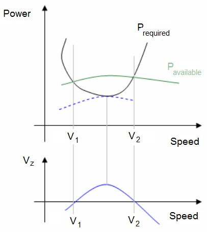
The graphs of available power and required power according to speed are then represented as curves used for the level flight.
By considering the known speed at each altitude, it is possible to plot the graph of power for a given altitude and thus deduce the curve of the climbing speed VZ.
On the diagram we can see that:
The climbing speed is zero for speeds V1 and V2.
The maximum climbing speed corresponds to a minimum required power.
The maximum climbing speed increases if Pavailable increases decreases if altitude decreases and decreases if the weight increases.
When altitude increases the curves Pavailable and Prequired change.
The lift and thrust equations change according to the density, and velocity increases.
2.2.2. Jet planes:
For the jet planes let us consider the equations of flight again.
But it is necessary to take the polar equation into consideration according to the Mach number.
By multiplying the thrust equation by the speed and by taking into consideration the lift equation we obtain:
The climbing speed is defined by the thrust of the engine, the mass and the aerodynamic efficiency of the aircraft.
![]()
Subsonic planes:
High climbing speed Vz is obtained when:
 is high,
The aerodynamic efficiency F is high.
For the planes with turbojets, the thrust decreases when altitude increases. The climbing speed also decreases.
Supersonic planes:
For supersonic aircrafts, we can always use the formula of VZ. Considering a small slope cosY equals to 1.

But the aerodynamic efficiency depends on the transonic value of the Mach number.
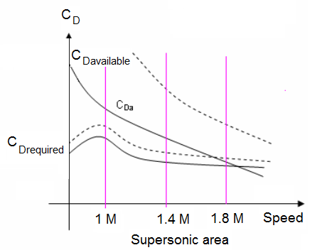
The use of the CD curve is more practical. It is necessary to distinguish between the two different cases, slightly supersonic and the highly supersonic aircrafts.
For a slightly supersonic aircraft, the maximum climbing speed is obtained for a Mach number corresponding to the beginning of the increase in CD.
For a highly supersonic aircraft, the maximum climbing speed can be reached for high Mach numbers.
For a slightly supersonic plane, the ceiling of flight is reached in subsonic flight. On the other hand for a highly supersonic plane the ceiling is obtained in supersonic or subsonic regions following the shapes of the CD curve.
2.3. Descent stable speed:
Consider a straight and level flight. Practically, let us take the case of a glider or an aircraft with an engine breakdown.
The equations of the flight are written: as:
For a glider there is no frictional force, only the aerodynamic loads and the weight are taken into consideration. In calm air, a glider can only go down. By combining the two equations, we obtain:

For the glider, the slope of its flight path is directly related to the aerodynamic efficiency. At any altitude, the maximum range can be achieved with a minimum angle of slope .
We notice that neither the weight nor wing surface area are affected by the distance, only the aerodynamic properties of the aircraft allow long distance travel, from a given altitude.
Effect on descent rate
The rate of descent VZ is equal to:

It is seen here that the ratio S/Mg has an influence on the rate of descent.
When traveling in calm air, the pilot must keep the aircraft at an angle of attack for maximum aerodynamic efficiency and the indicated air speed according to the weight of the plane. A decrease in weight does not affect the rate of descent. Only the diving speed decreases, Therefore the duration of the flight increases. For tail wind or head wind, we have the same conclusions.
a)Tail wind:
The slope is smaller,
The range is larger,
The angle of attack is larger,
The rate of descent is lower,
The true air speed is smaller.
b) Head wing:
For a head wind the results are inverted. But the pilot should not decrease the weight of the aircraft, instead he should rather overload it.
3. PERFORMANCES:
For the study of performances, we consider the aircraft in a straight and level flight. The Velocity Vector is in the symmetry plane of the aircraft and the thrust is parallel to the velocity. Generally, we assume that the air is not moving with respect to the ground.
3.1. Thrust diagram:
The manufacturer gives the curve with the available thrust for the engine. The polar curve gives CL and the angle of attack according to CD. From the Polar curve and available thrust curves it is possible to know the required thrust.
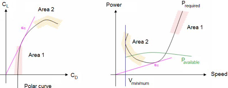
At high speeds, the value of CL is low. Although CL varies a lot, CD changes very little.
Characteristics:
At low speeds, the value of CL is important. The variations are opposite with the small change of CL, CD changes a lot.
Between areas 1 and 2, the value of Prequired passes through a minimum point. This minimum point corresponds to the maximum aerodynamic efficiency of the flight.
There is also a minimum speed Vminimum but there is no lift at this speed.
Utilization:
When plotting on the same graph, the required thrust and the available thrust, we obtain at various intersections the cruising speed. By substituting these speed values into the lift and thrust equation, we obtain values for CL and CD. It is used for turbine engine aircraft.
3.2. Power diagram:
Propeller planes are generally characterized by the torque of the propeller. Thus, we use the power of the engine.
The manufacturer gives the curve with the available power which can be used by the engine and the propeller (P, Prequired, and Pavailable). The polar curve gives the CL and the angle of attack according to CD. The thrust diagram gives the required power to oppose the drag.
From the polar and the available power curves, it is possible to plot a graph for the required power.
Characteristics:
At high speeds: the CD is almost constant.
At low speeds the value of the CL is significant.
Between areas 1 and 2, the value of Prequired passes through a minimum point. This minimum point corresponds to the maximum aerodynamic efficiency of the flight.
There is also a minimum speed Mminimum, and lift cannot be produced at this speed.
Utilization:
When plotting the required power and the available power on the same diagram, we obtain the various cruising speeds at various intersections.
By substituting these speed values in the lift and thrust equation, we directly have the values for CL and CD. These can be used for propeller planes.
Remark:
The two methods which we have previously seen apply to the subsonic region. During flights at high altitudes or faster speed, the variation of the polar curve complicates calculations. The method that takes into consideration the drag coefficient diagram has its advantages.
3.3. Performance range:
For the study of the range, we consider the established climb rate and the point of no return of the aircraft from its starting point. The range will be maximum if the fuel consumption to speed of flight ratio is minimum.
For a propeller plane, the range depends on the weight and the angle of attack. The flight with an angle of attack for maximum aerodynamic efficiency makes it possible to cover larger distances.
For a jet, the speed is significant.
Subsonic flight:
The angle of attack can be adjusted at different altitudes. At a given altitude, the pilot maintains a lower angle of attack, equal or higher than the angle of attack at maximum aerodynamic efficiency.
Transonic flight:
Thrust is increased thus increasing ground speed. Consequently an increase in range is obtained. But CD increases sharply according to the Mach number. The range is maximum for an angle of attack close to the maximum aerodynamic efficiency and a Mach number at the beginning of the increase in CD.
Supersonic flight:
The range depends on a given speed at a given altitude for each weight of the aircraft.
3.4. Autonomy and range:
Autonomy is the duration of the flight.
Taking speed, altitude and the flying conditions to be known at all times, the mass of the plane decreases constantly, because of the fuel consumption. We assume that the pilot takes into consideration the altitude at all times and the speed relative to instantaneous masses of the aircraft.
We thus have the fuel consumption of the aircraft engines:
![]()
From speed:
![]()
The range is given by:
![]()
When we consider specific fuel consumption, as well as the thrust, we have:
For the propeller planes:
 which must be a minimum. depends on the weight and the angle of attack, but not on altitude. For a propeller aircraft the range will be obtained at an angle of attack for maximum aerodynamic efficiency. Altitude is taken into consideration only for the output power of the engine or the propeller.
For Jet aircrafts:
 must be minimum. But it is necessary to take the range into consideration.
In subsonic flight, if the altitude is limited, the pilot may find it beneficial to fly at the highest altitude with a smaller angle of attack than that for the maximum aerodynamic efficiency. If there is no limit for an altitude, the pilot must fly at an angle of attack greater than that for maximum aerodynamic efficiency, with a maximum continuous thrust.
In supersonic flight, specific fuel consumption cannot be considered constant, there is thus a different Mach speed and an optimal altitude for each weight.
3.5. Ceiling of lift:
Propeller planes:
It is necessary to take into consideration, the available power and required power graphs, from the study of straight and level flight.
The ceiling is reached when the two curves form a tangent with each other.
If available power increases, the ceiling increases.
If the weight of the aircraft is increased, the ceiling decreases.
An increase in the surface area, without affecting the weight of the aircraft, is favourable for an increase in ceiling. But since there is generally an increase in weight, it is an optimal surface allowing a maximum ceiling.
Jet aircraft:
For a supersonic aircraft there is theoretically no maximum ceiling of lift. However it is necessary to fly at high Mach numbers with a limiting altitude.
For a subsonic plane having a fixed mass, with a given Mach number, there is a maximum altitude of flight. This limit of the flight envelope exists whatever the power of the engine.