1. AERODYNAMIC EFFICIENCY:
The characteristics of a wing of an aircraft are identified by its aspect ratio (λ) which influences the aerodynamic output of the aerofoil, represented by the aerodynamic efficiency of the wing. This is the ratio of the lift to drag or simply the L/D ratio,
The aerodynamic efficiency is defined as being equal to the lift /drag ratio. Assuming that the wing has an angle of attack , α which corresponds to a point M on the polar curve. The figure immediately defines the angle, Y formed by OM and the lift axis, using the same scale for CD and CL. It is the angle formed by the aerodynamic resultant R and the average velocity.
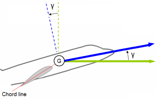
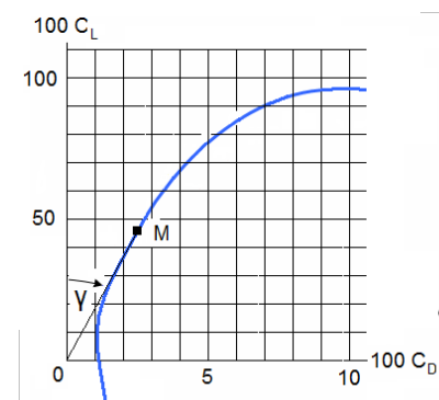
We have an immediate expression for the aerodynamic efficiency:
![]()
1.1. Gliding range:
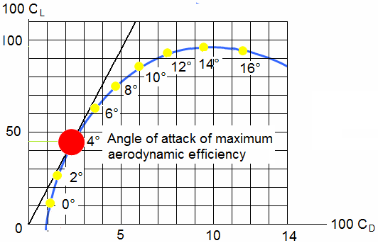
The aerodynamic efficiency characterises the "aerodynamic output ". It is maximum for a certain angle of attack called "optimal angle of attack ".
![]()
The comparison carried out on figure between the aerodynamic efficiency of an Sukkoi Jet 100 and that of a glider shows the difference in aerodynamic output. It is confirmed that the properties of span and surface area are the main factors considered for the qualities of the aerodynamic efficiency of the wing.
1.2. Maximum dynamic efficiency:
Lift increases proportionally with an increase in the angle of attack.
Drag changes with a change in the angle of attack; drag is low for slightly negative angles. Initially, drag increases slightly with an increase in the angle of attack and then as the angle keeps increasing, drag will increase more and more rapidly. The polar curve shows us the relation between lift and drag for each value of the angle of attack of the wing.
The ratio previously established thus allows us to see the effect of lift and drag. By using the polar curve, the aerodynamic efficiency is defined for each angle of attack. The aerodynamic efficiency is a characteristic of the quality of the wing; it gives the aerodynamic output of the wing at the desired point.
The maximum aerodynamic efficiency is obtained by projecting a line which passes through the origin, forming a tangent to the polar curve. The point of intersection gives the maximum lift for minimum drag at a given angle of attack.
1.3. Effect of the aerofoil:
The camber of the aerofoil and the shape of the mean camber line influence the value of the coefficient of lift CL.
Symmetrical aerofoils:
The value of CL max is less significant than for other aerofoils. The CL curve, depending on the angle of attack, is symmetrical with respect to the origin. These aerofoils are used for the empennage.
General purpose aerofoils:
These are the most commonly used aerofoils.
High lift aerofoils:
Especially used on hang-gliders, for a positive value of the pitching moment when lift is null.
1.4. Gliding examples:
Directly related to the aerodynamic efficiency, gliding will depend on the properties of each aircraft. To have a straight and level flight, the forces applied on the aircraft must be in equilibrium.
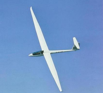
The glider:
The glider does not have an engine consequently, there is no thrust. The relationship between drag, lift and weight are applied when the glider is traveling at a certain speed due to the angle of descent.
Aerodynamic properties are directly related to the choices of the aerofoils so as to obtain the best value for the lift/drag ratio.
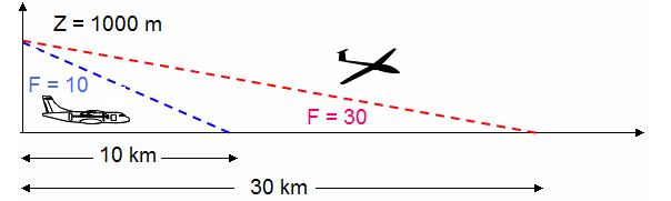
On a glider, the lift/drag ratio is about 20 to 60. A glider with a lift/drag ratio equal to 30 will be able to travel 30 km while losing an altitude of only 1 km.
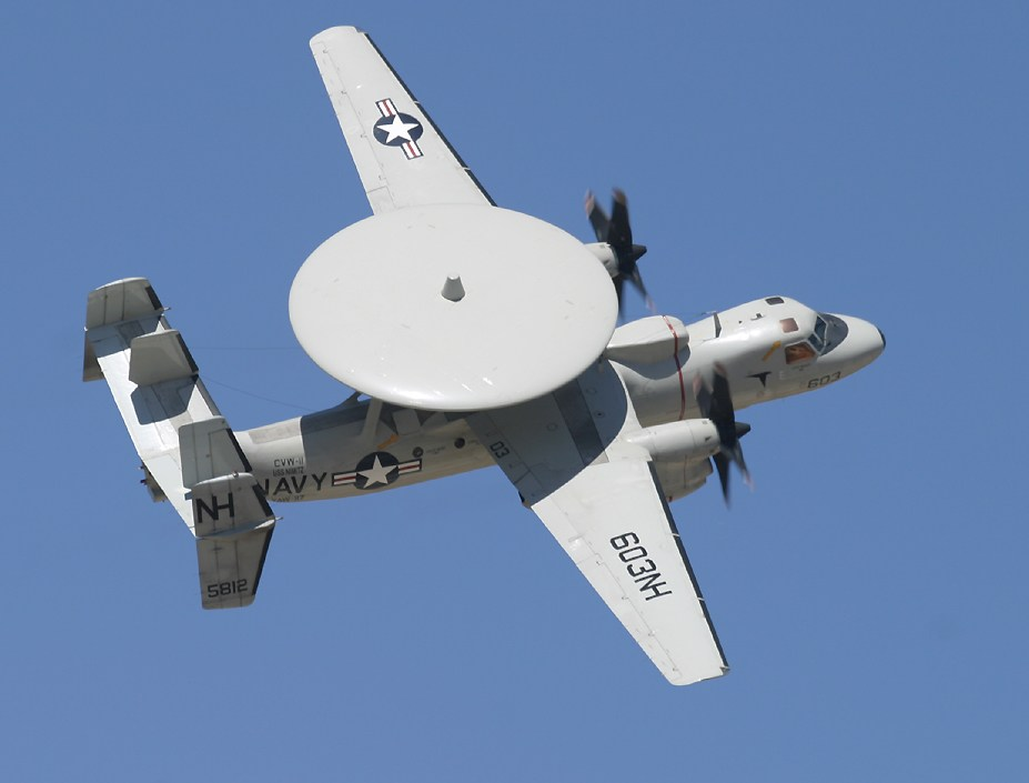
The E2C Hawkeye:
This is an aircraft with an aerodynamic efficiency of 8. In the best situation, with perfect climatic conditions, this aircraft will be able to travel a distance of 8000 m and lose an altitude of 1000 m.
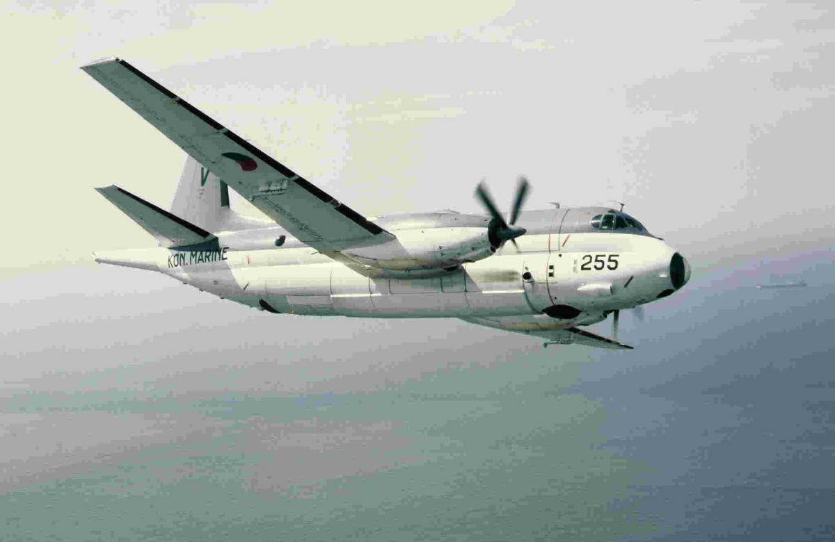
The Atlantic Breguet:
This aircraft is used for sea rescue and underwater expeditions.
As this aircraft operates far from the coasts, an engine breakdown could be fatal.
To limit the risks, an aerodynamic study made it possible to have an aerodynamic efficiency equal to 15. It is possible for this aircraft to travel 15 000 m for a loss in altitude of 1000 m.
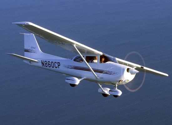
The Cessna:
The Cessna has a data sheet for the lift/drag ratio. This data represents the desired speed for a maximum aerodynamic efficiency.
2. THE EFFECT OF WIND ON GLIDING:
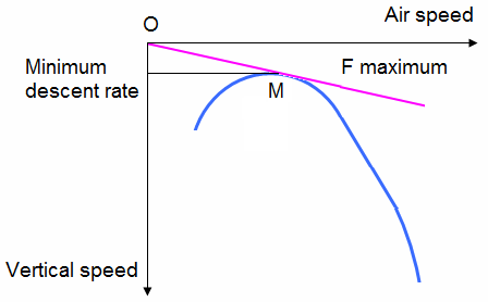
2.1. No wind:
Let us consider an aircraft with an engine failure.
The aircraft is moving and the pilot cannot use distance as a reference.
To manage his descent the pilot uses the information available on the aircraft, the speed of the aircraft or the indicated airspeed by the airspeed indicator and the rate of descent indicated by the rate of climb and descent indicator.
These two speeds on a graph give two curves known as the speed curves.
2.2. Tail wind:
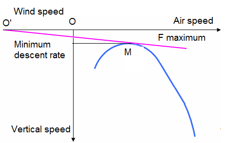
The wind is present and pushes the aircraft. On the preceding reference mark we only have to add on the speed axis of the aircraft the effect of the wind.
The origin of the tangent to the curve is shifted with respect to the reference mark. The origin O' of the tangent at the curve is different and negative of the precedent origin O.
When compared to the case where there was no wind. The slope is less steep, we have a larger range, the angle of attack is greater and the ground speed is higher.
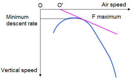
2.3. Head wind:
In the case of a head wind, the origin is moved towards the direction of the air speed.
Conclusion:
For the pilot, the angle of attack is the angle for maximum aerodynamic efficiency; the weight has only a secondary effect. Knowing the aerodynamic efficiency of an aircraft with the engine shut down allows us to obtain the range of the gliding flight.