LIFT AUGMENTATION
For an aircraft to take off, the lift must be higher than the weight. We saw that the equation for lift was:
![]()
For a given wing surface area S and a given coefficient of lift CL, it is necessary for the takeoff speed to be high enough when the weight of the aircraft is significant. Thus a longer runway will be needed to reach the necessary speed.
When landing, the low speed of the aircraft causes a decrease in lift. Consequently, when the lift reaches its minimum value, the wing will stall at a high angle of attack.
In order to maintain significant lift when flying at low speeds, it is necessary to consider two parameters:
S the wing surface area,
CL the coefficient of lift.
To increase the performances of the aircraft during takeoff and landing, and at the same time to limit the required distances of these phases of flight, it is necessary to equip the wing with devices able to compensate for the disadvantages caused at low speeds.
1. PRINCIPLE OF LIFT AUGMENTATION SYSTEM:
The lift must be temporarily increased at the time of takeoff and landing. It is on this principle that automatic or controlled devices known as high-lift devices are integrated into the aerodynamic structure of the plane.
1.1. Effect on the wing surface area (S):
The increase in wing surface area S is primarily obtained by the deployment of moveable surfaces at the leading edge and trailing edge of the wing. Some experiments were carried out on sliding wings with a variable span according to the desired flight phases, but these ideas were often abandoned.
1.2. Effect on the coefficient of lift (CL):
There are various means to increase the coefficient of lift:
By changing the curvature of the aerofoil, thus the chord line and the angle of incidence. Indeed it is the deployment of moveable surfaces which changes the geometry of the aerofoil.
By actions on the boundary layer: the layers of air on the upper surface have a tendency to separate from the aerofoil at low speeds.The remedy consists of energizing the boundary layer so that it adheres to the skin of the aerofoil, thus producing lift.
2. LEADING EDGE LIFT AUGMENTATION SYSTEMS:
The wind tunnel tests showed that the lift coefficient of an aerofoil depends on several parameters. The characteristics of the aerofoil and its angle of attack are very important in order to obtain an increase in lift. By increasing the camber of the aerofoils while increasing the wing surface area, lift will be improved for low speeds.
2.1. Leading edge slats:
Slats are aerodynamic surfaces on the leading edge of the wings of fixed-wing aircraft which, when deployed, allow the wing to operate at a higher angle of attack.
While passing through the convergent channel, the airflow is accelerated on the lower surface towards the upper surface thus making it possible to limit the separations of the boundary layer where the angle of attack is high as well as on the rest of the aerofoil.
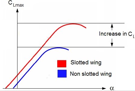
2.2. Variation of CL at leading edge according to the angle of attack:
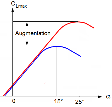
All the lift augmentation systems at the leading edge make it possible to increase the CL max by increasing the angle of attack.
A higher coefficient of lift is produced as a product of angle of attack and speed, so by deploying slats an aircraft can fly more slowly or take off and land in a shorter distance.
They are usually used while landing or performing maneuvers which take the aircraft close to the stall, but are usually retracted in normal flight to minimize drag.
Below: an A319 at landing: slats deployed:

2.3. The three slat effects:
The slat effect: The velocities at the leading edge of the downstream element are reduced due to the circulation of the upstream element (slat) thus reducing the pressure peaks of the downstream element.
The circulation effect: The circulation of the downstream element increases the circulation of the upstream element thus improving its aerodynamic performance.
The dumping effect: The discharge velocity at the trailing edge of the slat is increased due to the circulation of the main airfoil thus alleviating separation problems or increasing lift
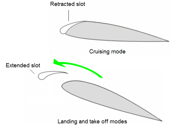
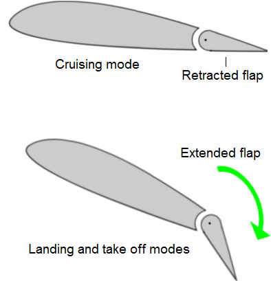
2.4. Leading edge augmentation lift principle:
Cruise mode, slat retracted:
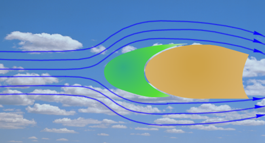
Landing and take off positions, flap retracted:
In landing or take off mode, the pilot increases the angle of attack. It results a lift augmentation. The drag is also increasing.
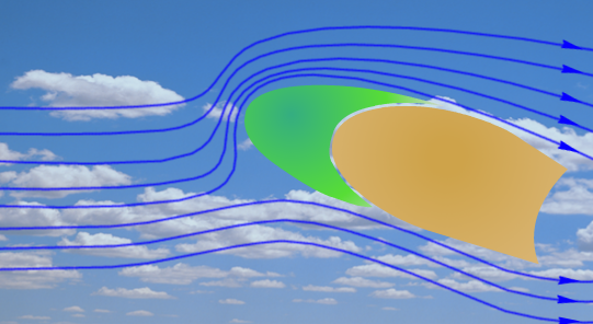
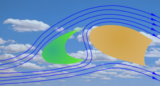
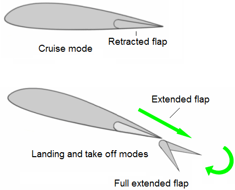
Landing and take off positions, flap extended:
The high pressured air coming from the lower surface emerges at high speed on the upper surface and accelerates the boundary layer. The lift is increased.
2.5. Leading edge augmentation lift systems:
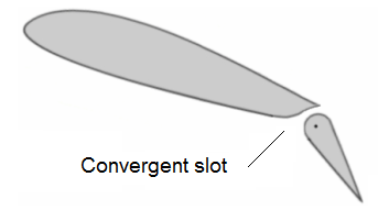
Slotted wing:
It can be fixed, automatic or having its extension controlled. A shaped flap is placed at the leading edge to create a convergent aerodynamic airflow.
The difference in pressure between the lower surface and the upper surface creates an airflow which speeds up the boundary layer thus causing the separation to be retarded.
Krueger flap:
While the aerodynamic effect of Krueger flaps is similar to that of slats or slots, they are deployed differently. Krueger flaps, hinged at their leading edges, hinge forwards from the under surface of the wing, increasing the wing camber and maximum coefficient of lift.
This kind of flap rotates around an axis at the leading edge of the wing; it extends the aerofoil forward and folds up on the lower surface, thus causing an increase in the wing surface area.
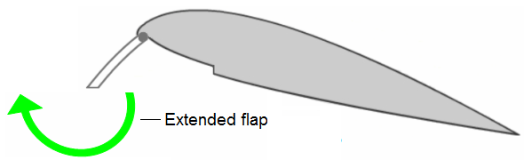
This device can operate in different ways. One way consists of a sliding flap, by means of rollers, extending at the leading edge. This mechanism is called a “betz” flap.
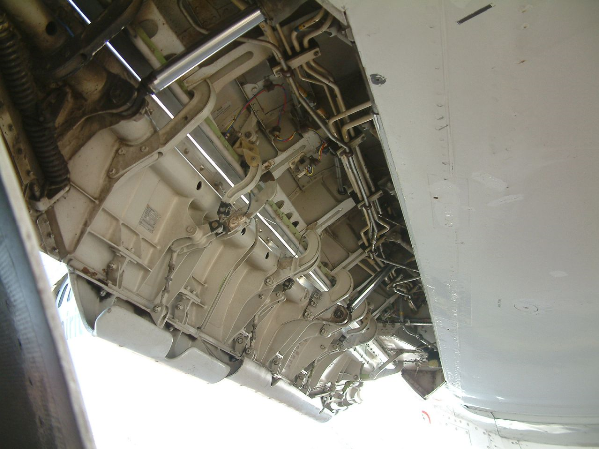
Below: Krueger flaps extended:
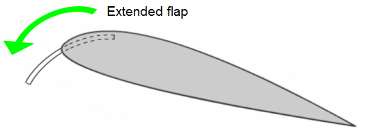
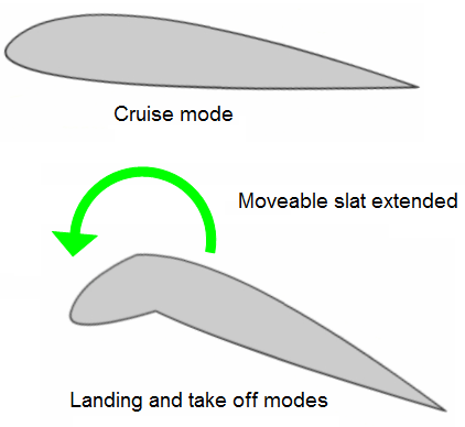
Moveable slats:
The rotation of the front part of the aerofoil around a hinge increases the camber of the aerofoil.
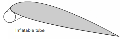
Pneumatic system:
An inflatable rubber tube is pressurized and placed at the leading edge. The rubber tube, once deflated, adheres to the surface of the aerofoil.
3. LEADING EDGE LIFT AUGMENTATION SYSTEMS:
3.1. Trailing edge flaps:
Flaps give a new shape to the wing but their deployment is limited by the separation of the boundary layer. The presence of slits, whose form and position were calculated and studied by engineers, accelerates the airflow on the upper surface in order to make them stick to the aerofoil .
The split flap:
This type of flap affects the flow only on the lower surface. The increase in pressure caused by the extension of this device at the lower surface increases lift. The significant wake that it produces also causes a great increase in drag.
The plain or camber flap:
This flap affects the airflow on the lower surface and the upper surface of the aerofoil by modifying its shape without much increase in drag. The risk in separation of the boundary layer is however increased.
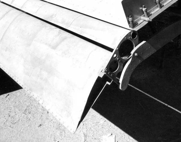
The Fowler flaps:
The extension and retraction of this flap are carried out simultaneously by moving its axis of rotation. This change can cause a great increase in the wing surface area.
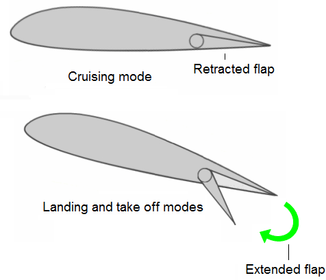
The slotted flap:
The prevention of the separation of the boundary layer is achieved by the presence of a slot between the fixed part of the wing and the leading edge of the flap causing an acceleration of the airflows.
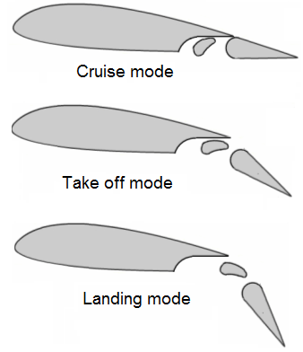
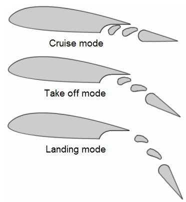
Multi slotted flaps:
With this type of flap acting itself as a lift augmentation system, the increase in lift is very significant. The airflow separation is delayed to a maximum by the presence of converging slots which therefore control the boundary layer.
The shape of the flaps changes gradually to adapt their position to the flight configuration.
Below: Double slotted flap:
Below: Double slotted flap:
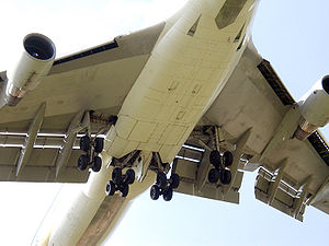
Below: Triple slotted flap
Below: B 747 triple slotted flap
3.2. Factors affecting the boundary layer:
Blowing:
Bleed air from the compressor section is blown at the trailing edge, thus providing kinetic energy to the boundary layer.
Suction:
On the upper surface of the wing, the boundary layer is sucked in, causing it to adhere to the surface of the aerofoil.
Blowing at the trailing edge:
This process known as JET FLAP consists of blasting air at the trailing edge to deviate the airflow as well as to accelerate it.
3.3. Means of decreasing lift and air brakes:
The purpose of decreasing lift is to decrease CL and the purpose of the airbrakes is to increase CD. These two systems make it possible to increase the angle of descent, to decrease speed and therefore decrease the landing roll.
The various types:
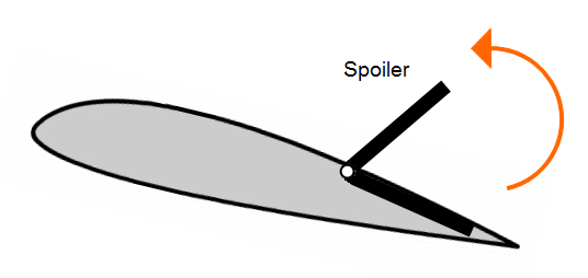
Spoilers:
They are retractable flaps placed symmetrically on the upper surface of the wings to destroy lift. They can be actuated symmetrically or asymmetrically (to contribute to the roll control when combined with the ailerons).
Air-brakes:
These are aerodynamic brakes in the form of panels which are deployed in a symmetrical way in the airflow. They can be deployed at various positions depending on the amount of braking required.
Below: Air-brakes extended:
The air-brakes considerably increase the aerodynamic resistance of the plane.
These devices make it possible to change altitude quickly and to maintain a cruising altitude while approaching the airport, thus diminishing the fuel consumption.
Air brakes are designed so that lift is not considerably decreased. At touch down, during landing, while fully extended, they contribute with the help of the spoilers to decreasing the landing roll.