DIODE PARAMETERS: PEAK INVERSE VOLTAGE, MAXIMUM FORWARD CURRENT, TEMPERATURE, FREQUENCY, LEAKAGE CURRENT, POWER DISSIPATION
1. MAXIMUM FORWARD CURRENT:
One of the two main parameters for any diode is the maximum current it can carry in the forward direction (conduction). This is always an average number, to take into account varying currents such as when the diode is rectifying at frequency F.
Peak forward current may be 10 to 100 times higher but only for a few milliseconds and a short duty cycle.
LEDs and laser diodes are a special case where the forward current determines brightness. If is usually between 1mA and 20mA for a LED and up to 250mA and more for a laser diode but can be 1A and more for pump laser diodes. Be very careful not to exceed ![]() .
.
For most diodes, ![]() can be from 10mA (small signal) to 100A but can go as high as many KA (as in kilo-amps).
can be from 10mA (small signal) to 100A but can go as high as many KA (as in kilo-amps).
Exceeding ![]() may result in overheating and meltdown of the diode.
may result in overheating and meltdown of the diode.
2. PEACK INVERSE VOLTAGE (PIV):
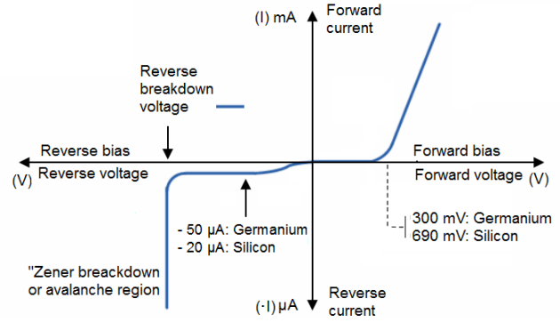
The second main parameter for any diode is the maximum reverse [breakdown] voltage or the Peak Inverse Voltage, (PIV),.
The ability of a diode to withstand reverse-bias voltages is limited, like it is for any insulating substance or device. If the applied reverse-bias voltage becomes too great, the diode will experience a condition known as breakdown, which is usually destructive. A diode's maximum reverse-bias voltage rating is known as the Reverse Breakdown Voltage and may be obtained from the manufacturer.
Up to, the diode presents a reasonably high resistance to the circuit. As the [reverse] voltage approaches PIV, the apparent resistance will drop and current will start to rise. Above PIV, the diode will conduct quite nicely and so conduct current as the circuit allows. This combination of voltage and current can create high power dissipation in the diode, resulting in overheating and meltdown of the device.
Common PIV is from 25V to 1KV but can range up to 10's of KV.
Like forward voltage, the PIV rating of a diode varies with temperature, except that PIV increases with increased temperature and decreases as the diode becomes cooler, exactly opposite that of forward voltage.
3. TEMPERATURE AND THERMAL RESISTANCE:
3.1. Operating junction temperature:
Operating junction temperature = TJ, the maximum allowable temperature for the diode's PN junction, usually given in degrees Celsius (oC). Heat is the "Achilles' heel" of semiconductor devices: they must be kept cool to function properly and give long service life.
3.2. Storage temperature range:
Storage temperature range = TSTG, the range of allowable temperatures for storing a diode (unpowered).
Sometimes given in conjunction with operating junction temperature (TJ), because the maximum storage temperature and the maximum operating temperature ratings are often identical.
If anything, though, maximum storage temperature rating will be greater than the maximum operating temperature rating.
3.3. Thermal resistance and power dissipation:
Thermal resistance = R (Θ), the temperature difference between junction and outside air (R (Θ)JA) or between junction and leads (R (Θ)JL) for a given power dissipation.
Expressed in units of degrees Celsius per watt (oC/W).
Ideally, this figure would be zero, meaning that the diode package was a perfect thermal conductor and radiator, able to transfer all heat energy from the junction to the outside air (or to the leads) with no difference in temperature across the thickness of the diode package.
A high thermal resistance means that the diode will build up excessive temperature at the junction (where it's critical) despite best efforts at cooling the outside of the diode, and thus will limit its maximum power dissipation.
Maximum total dissipation = PD, the amount of power (in watts) allowable for the diode to dissipate, given the dissipation (P = IE) of diode current multiplied by diode voltage drop, and also the dissipation (P = RI2) of diode current squared multiplied by bulk resistance.
Fundamentally limited by the diode's thermal capacity (ability to tolerate high temperatures).
3.4. Maximum reverse current (Leakage current):
Maximum reverse current (Leakage current) = IR, the amount of current through the diode in reverse-bias operation, with the maximum rated inverse voltage applied (VDC).
3.5 Frequency.
Sometimes certain diodes must be used in frequency ranges.
Semiconductor manufacturers provide detailed specifications on their products in publications known as datasheets. Datasheets for a wide variety of semiconductor components may be found in reference books and on the internet. I personally prefer the internet as a source of component specifications because all the data obtained from manufacturer websites are up-to-date.
A typical diode datasheet will contain figures for the all parameters.
