DETAILED OPERATION AND CHARACTERISTICS OF VARACTOR DIODES
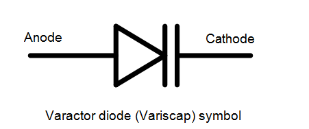
The varactor diode or varicap diode consists of a standard PN junction, although it is obviously optimised for its function as a variable capacitor. In fact ordinary PN junction diodes can be used as varactor diodes, even if their performance is not to the same standard as specially manufactured varactors.
1. OPERATION:
The basis of operation of the varactor diode is quite simple.
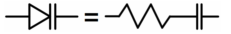
The diode is operated under reverse bias conditions and this gives rise to three regions. At either end of the diode are the P and N regions where current can be conducted. However around the junction is the depletion region where no current carriers are available. As a result, current can be carried in the P and N regions, but the depletion region is an insulator.
This is exactly the same construction as a resistor + a capacitor.
The resistance R depends of the type of junction and materials used.
The capacitance C of a capacitor is dependent on a number of factors including the plate area, the dielectric constant of the insulator between the plates and the distance between the two plates. In the case of the varactor diode, it is possible to increase and decrease the width of the depletion region by changing the level of the reverse bias.
This has the effect of changing the distance between the plates of the capacitor.
5.2. Varactor Q:
An important characteristic of any varactor diode is its Q. This is particularly important in a number of applications. For oscillators used in frequency synthesizers it affects the noise performance.
High Q diodes enable a higher Q tuned circuit to be achieved, and in turn this reduces the phase noise produced by the circuit. For filters the Q is again very important. A high Q diode will enable the filter to give a sharper response, whereas a low Q diode will increase the losses.
The Q is dependent upon the series resistance that the varactor diode exhibits. This resistance arises from a number of causes:
the resistance of the semiconductor in the areas outside the depletion region, i.e. in the region where the charge is carried to the "capacitor plates",
some resistance arising from the lead and package elements of the component,
some contribution from the die substrate.
The Q or quality factor for the diode can be determined from the equation below:
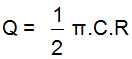
Where:
C: the capacitance at the measured voltage,
R: the series resistance.
5.3. Abrupt and hyperabrupt varactor diodes:
Some varactor diodes may be referred to as abrupt and hyperabrupt types. The terms of abrupt varactor diode, or hyperabrupt varactor diode refers to the properties of the varactor diode junction.
The abrupt varactor and hyperabrupt varactor diodes differ in the ways that thee junctions are fabricated. This gives significant differences in the performance of the two types of varactor diode.
Abrupt varactor diodes:
Abrupt varactor diodes are the more commonly used for of diode. As the abruptness of the junction is governed by the doping concentration and also the profile, this is controlled during the manufacture. For an abrupt varactor diode the doping concentration is held constant, i.e. constant doping level as far as reasonably possible.
The abrupt varactor exhibits an inverse square law C-V function. This provides for inverse fourth law frequency dependence. In applications where a linear dependence is required, a lineariser is needed. This takes additional circuitry that may be an additional burden for some applications, not only in terms of circuitry, but also the slower response speed caused by the lineariser.
Hyperabrupt varactor diodes:
Hyperabrupt junctions provide a C-V curve that has an inverse square law curve over at least some of the characteristic. This provides a narrow band linear frequency variation.
In addition to this the hyperabrupt junction gives a much greater capacitance change for the given voltage change.
The advantages of the hyperabrupt varactor come at a cost as there is a substantial reduction in Q when compared to abrupt varactor diode. As a result hyperabrupt diodes are generally only used at lower microwave frequencies up to a few GHz at most.
5.4. Varactor applications:
In general, varactors are used to replace the old style variable capacitor tuning. They are used in tuning circuits of more sophisticated communication equipment and in other circuits where variable capacitance is required. One advantage of the varactor is that it allows a DC voltage to be used to tune a circuit for simple remote control or automatic tuning functions.
Varactor diodes are also used in oscillators applications.