DETAILED OPERATION AND CHARACTERISTICS OF LIGHT EMITTING DIODES (LED)
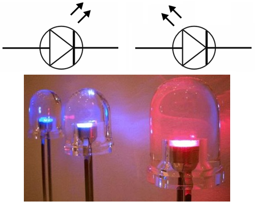
1. LED SYMBOL:
The schematic symbol for an LED is a regular diode shape inside of a circle, with two small arrows pointing away (indicating emitted light).
2. LED TECHNOLOGY:
The positive power is applied to one side of the LED semiconductor through a lead (anode) and a whisker. The other side of the semiconductor is attached to the top of the anvil that is the negative power lead (cathode).
It is the chemical makeup of the LED semiconductor that determines the colour of the light the LED produces.
The epoxy resin enclosure has three functions. It is designed to allow the most light to escape from the semiconductor, it focuses the light (view angle), and it protects the LED semiconductor from the elements.
The entire unit is totally embedded in epoxy. This is what make LEDs virtually indestructible. There are no loose or moving parts within the solid epoxy enclosure.
Therefore, a light-emitting diode (LED) is essentially a PN junction semiconductor diode that emits light when current is applied. By definition, it is a solid-state device that controls current without heated filaments and is therefore very reliable.
Each chemical element has its own "signature" emission of radiant energy when its electrons "jump" between different, quantized energy levels.
This is what makes spectrographic identification of elements possible.
Electrons flowing through a PN junction experience similar transitions in energy level, and emit radiant energy as they do so.
The frequency of this radiant energy is determined by the crystal structure of the semiconductor material, and the elements comprising it. Some semiconductor junctions, composed of special chemical combinations, emit radiant energy within the spectrum of visible light as the electrons transition in energy levels.
Simply put, these junctions glow when forward biased. A diode intentionally designed to glow like a lamp is called a light-emitting diode, or LED.
Diodes made from a combination of the elements gallium, arsenic, and phosphorus (called gallium-arsenide-phosphide) glow bright red, and are some of the most common LEDs manufactured.
By altering the chemical constituency of the PN junction, different colors may be obtained.
LED performance is based on a few primary characteristics.
3. LED COLORS:
LEDs are highly quasi-monochromatic, emitting a quasi-pure colour in a narrow frequency range. The colour emitted from an LED is identified by peak wavelength and measured in nanometers (nm).
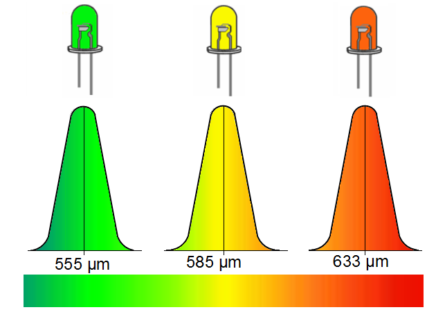
Peak wavelength is a function of the LED chip material.
The dominant wavelength is obtained from the colour coordinates discussed above. It is essentially the colour that is actually perceived by the human eye. The peak wavelength is the wavelength at the maximum spectral intensity.
The peak value is easy to obtain and is therefore the most common value specified by LED manufacturers, however, it has little practical significance for applications that are viewed with the human eye since two LEDs may have the same peak wavelength but can be perceived as different colors
Currently, the most accurate method for measuring colour is by using a spectroradiometer. This device performs a complete spectral power distribution of the source being measured from which all photometric, radiometric and colorimetric parameters can be mathematically calculated. The wavelength accuracy of the equipment should be better than 0.5nm with 0.1nm preferred.
LEDs are made from gallium-based crystals that contain one or more additional materials such as phosphorous to produce a distinct colour.
Different LED chip technologies emit light in specific regions of the visible light spectrum and produce different intensity levels.
a) Finding the frequency from the wavelength of light.
The frequency of light is related to the wavelength of light in a very simple way. The spectrometer can be used to examine the light from the LED, and to estimate the peak wavelength of the light emitted by the LED.
But we prefer to have the frequency of the peak intensity of the light emitted by the LED. The wavelength is related to the frequency of light by , where c is the speed of light (3 x 10⁸ m/s) and λ is the wavelength of light read from the spectrometer.
Suppose you observed the red LED through the spectrometer, and found that the LED emits a range in colors with maximum intensity corresponding to a wavelength as read from the spectrometer of λ = 660 x 10-9 m.
The corresponding frequency at which the red LED emits most of its light is:
![]()
4. LED CHARACTERISTICS:
The characteristic current-voltage of LED depends monthly of the wavelength of light.
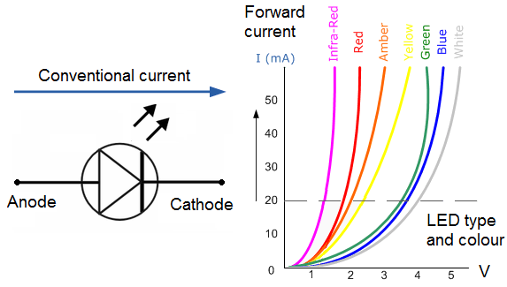
Table below shows typical technical data for some LEDs with diffused packages (plastic bodies).
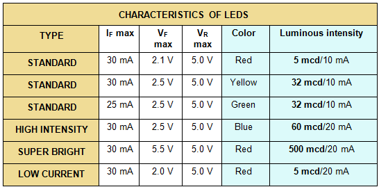
IF max: Maximum forward current, forward just means with the LED connected correctly. This is about 2V, except for blue and white LEDs for which it is about 4V.
VF max: Maximum forward voltage.
VR max: Maximum reverse voltage. You can ignore this for LEDs connected the correct way round.
5. WHITE LED TECHNOLOGY:
Because red, blue, and green lights, mixed in varying quantities, can duplicate any colour sensation, they are called primary additive colors. Equal intensities of all three lights added together produce the sensation of white light.
However, to achieve this combination with a mixture of red, green, and blue LEDs requires a sophisticated electro-optical design to control the blend and diffusion of colours. Variations in LED colour and intensity further complicate this approach.
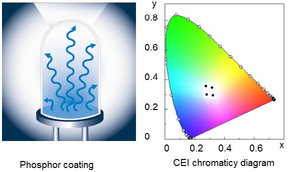
White LED product line is based on a single LED chip with a phosphor coating
Phosphor emits white light when struck by blue or ultraviolet photons. Fluorescent bulbs work by a similar principle; ultraviolet emission from an electric discharge in the tube causes the phosphor to shine white.
Although the white LED process produces various hues, variation can be controlled through screening. White LED products are screened based on four specific chromaticity coordinates nearest to the center of the CIE diagram.
The CIE diagram depicts all possible colour coordinates on or inside the horseshoe curve. Pure colors lie on the curve, whereas the white point is in the center. The four points depicted in the center of the graph represent the white LED output color.
Although the four x/y coordinates are close to pure white, white LEDs are generally not effective as a universal light source to illuminate colored lenses.
White LEDs are primarily useful to backlight opaque, white, or clear lenses. As this technology continues to improve, white LEDs will surely gain popularity as a source of illumination as well as indication.
6. LUMINOUS INTENSITY AND DIRECTIONAL CHARACTERISTICS:
LED light output varies with the type of chip, encapsulation, efficiency of individual wafer lots and other variables. Several LED manufacturers use terms such as "super-bright," and "ultra-bright" to describe LED intensity. Such terminology is entirely subjective, as there is no industry standard for LED brightness.
Luminous intensity is roughly proportional to the amount of current supplied to the LED.
The greater the current gives the higher the intensity.
6.1. Measuring LED intensity:
Since LEDs are highly directional, light output can be measured at a single point. This on-axis luminous intensity value (Iv) is generally rated in terms of millicandela (mcd).
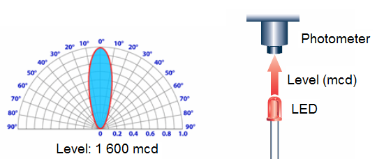
Luminous intensity is measured in millicandela (mcd) and the radiance is measured in Watts/steradian (W/sr) (one steradian is the solid angle at the center of a one-meter-radius sphere subtended by a square meter of surface area).
The steradian is a metric unit.
The radiance of light is the amount of luminous flux propagated in a given solid angle, or the amount of incident.
Hence, as Figure shows, the narrower the directionality of an LED lamp, the higher the luminous intensity of that lamp. For a LED lamp of given directionality, the higher the emission efficiency of the chip, the higher the luminous intensity.
6.2. Eye safety information:
The need to place eye safety labeling on LED products is dependent upon the product design and the application. Only a few LEDs produce sufficient intensity to require eye safety labelling. However, for eye safety, do not stare into the light beam of any LED at close range.
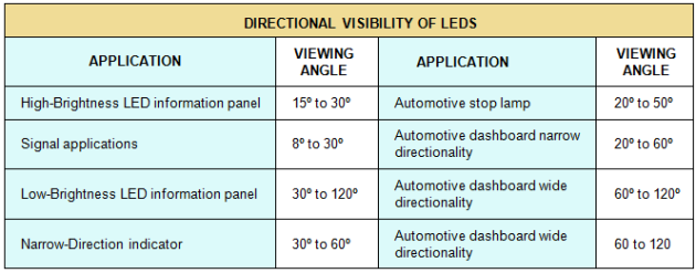
6.3. Visibility:
Luminous intensity does not represent the total light output from an LED. Both the luminous intensity and the spatial radiation pattern (viewing angle) must be taken into account. If two LEDs have the same luminous intensity value, the lamp with the larger viewing angle will have the higher total light output. Directional Characteristics As described above, the same LED chip can be used in the products of different LED manufacturers so that a lamp has different directional characteristics.
Table provides a list of useful criteria for LED lamps.
Overall visibility can be enhanced by increasing the number of LED chips in the encapsulation, increasing the number of individual LEDs, and utilizing secondary optics to distribute light.
To illustrate, consider similar red LED chip technology in four different configurations:
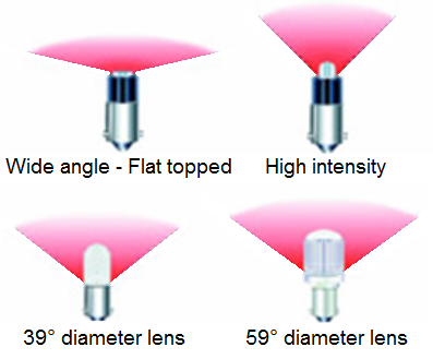
In each case, the amount of visible light depends on how the LED is being viewed.
The single chip may be appropriate for direct viewing in competition with high ambient light. The 6-chip may be better suited to backlight a switch or small legend, while LED may be best to illuminate a pilot light or larger lens.
6.4. Voltage/Design current:
LEDs are current-driven devices, not voltage driven. Although drive current and light output are directly related, exceeding the maximum current rating will produce excessive heat within the LED chip due to excessive power dissipation. The result will be reduced light output and reduced operating life.
LEDs that are designed to operate at a specific voltage contain a built-in current-limiting resistor. Additional circuitry may include a protection diode for AC operation or full-bridge rectifier for bipolar operation. The operating current for a particular voltage is designed to maintain LED reliability over its
LEDs of all colors are available in uncolored packages which may be diffused (milky) or clear (often described as 'water clear'). The colored packages are also available as diffused (the standard type) or transparent.
6.5. Connecting LEDs:
LEDs must be connected the correct way round, the diagram may be labelled A (or +) for anode and K (or -) for cathode.
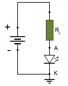
The cathode is the short lead and there may be a slight flat on the body of round LEDs. If you can see inside the LED the cathode is the larger electrode (but this is not an official identification method).
6.6. Series connections:
A LED must have a resistor connected in series to limit the current through the LED, otherwise it will burn out almost instantly.
The resistor value, R is given by: 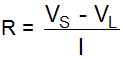
VS = supply voltage
VL = LED voltage (usually 2V, but 4V for blue and white LEDs)
I = LED current (e.g. 20mA), this must be less than the maximum permitted.
If the calculated value is not available choose the nearest standard resistor value which is greater, so that the current will be a little less than you chose. In fact you may wish to choose a greater resistor value to reduce the current (to increase battery life for example) but this will make the LED less bright.
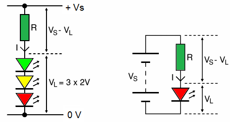
6.7. Avoid connecting LEDs in parallel:
Connecting several LEDs in parallel with just one resistor shared between them is generally not a good idea.
If the LEDs require slightly different voltages only the lowest voltage LED will light and it may be destroyed by the larger current flowing through it.
Although identical LEDs can be successfully connected in parallel with one resistor this rarely offers any useful benefit because resistors are very cheap and the current used is the same as connecting the LEDs individually.
If LEDs are in parallel each one should have its own resistor.
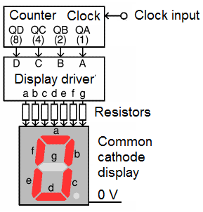
6.8. 7-segment display drivers:
The inputs A-D of a display driver are connected to the BCD (binary coded decimal) outputs QA-D from a decade counter. A network of logic gates inside the display driver makes its outputs a-g become high or low as appropriate to light the required segments a-g of a 7-segment display.
A resistor is required in series with each segment to protect the LEDs, 330 is a suitable value for many displays with a 4.5V to 6V supply.
There are two types of 7-segment displays:
Common Anode (CA or SA) with all the LED anodes connected together. These need a display driver with outputs which become low to light each segment, for example the 7447. Connect the common anode to +Vs.
Common Cathode (CC or SC) with all the cathodes connected together. These need a display driver with outputs which become high to light each segment, for example the 4511. Connect the common cathode to 0V.
The common anode/cathode is often available on 2 pins. Displays also have a decimal point (DP) but this is not controlled by the display driver. The segments of larger displays have two LEDs in series. For display connections please see your supplier's catalogue or manufacturer's datasheet.
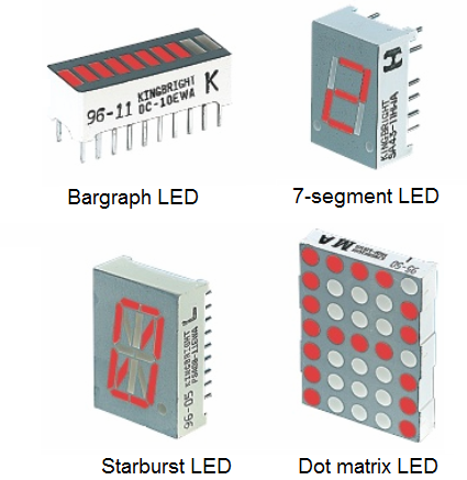
LED displays are packages of many LEDs arranged in a pattern, the most familiar pattern being the 7-segment displays for showing numbers (digits 0-9). The pictures below illustrate some of the popular designs:
6.9. Other applications of LEDs:
LEDs offer benefits in terms of maintenance and safety.
The typical working lifetime of a device, including the bulb, is ten years, which is much longer than the lifetimes of most other light sources.
Further, LEDs fail by dimming over time, rather than the abrupt burn-out of incandescent bulbs. LEDs give off less heat than incandescent light bulbs and are less fragile than fluorescent lamps. Since an individual device is smaller than a centimetre in length, LED-based light sources used for illumination and outdoor signals are built using clusters of
Because they are monochromatic, LED lights have great power advantages over white lights where a specific colour is required. Unlike the white lights, the LED does not need a filter that absorbs most of the emitted white light. Coloured fluorescent lights are made, but they are not widely available.
LED lights are inherently coloured, and are available in a wide range of colours. One of the most recently introduced colours is the emerald green (bluish green, about 500 nm) that meets the legal requirements for traffic signals and navigation lights.
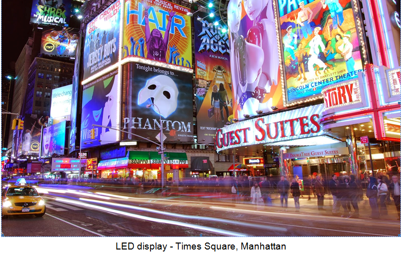
The largest LED display in the world is 36 metres high (118 feet), at Times Square, Manhattan. The metre is the basic unit of length in the International System of Units (SI). ... Times Square Times Square is also the name of a station on the Detroit People Mover, a shopping mall in Hong Kong, and a 1980 movie. ... Manhattan is an island bordering the lower Hudson River. ...
There are applications that specifically require light that does not contain any blue component.
Examples are photographic darkroom safe lights, illumination in laboratories where certain photo-sensitive chemicals are used, and situations where dark adaptation (night vision) must be preserved, such as cockpit and bridge illumination, observatories, etc.
Yellow LED lights are a good choice to meet these special requirements because the human eye is more sensitive to yellow light (about 500 lm/watt emitted) than that emitted by the other LEDs.
Here is a list of known applications for LEDs, some of which are further elaborated upon in the following text:
in general, commonly used as information indicators in various types of embedded systems (many of which are listed below),
thin, lightweight message displays, e.g. in public information signs (at airports and railway stations, among other places),
red LEDs have been used to replace incandescent bulbs in railroad crossing lights,
status indicators, e.g. on/off lights on professional instruments and consumers audio/video equipment,
infrared LEDs in remote controls (for TVs, VCRs, etc),
clusters in traffic signals, replacing ordinary bulbs behind colored glass,
car indicator lights and bicycle lighting; also for pedestrians to be seen by car traffic,
calculator and measurement instrument displays (seven segment displays), although now mostly replaced by LCDs,
red or yellow LEDs are used in indicator and [alpha]numeric displays in environments where night vision must be retained: aircraft cockpits, submarine and ship bridges, astronomy observatories, and in the field, e.g. night time animal watching and military field use,
red or yellow LEDs are also used in photographic darkrooms, for providing lighting which does not lead to unwanted exposure of the film,
illumination, for example, flashlights (US) / torches (UK), and backlights for LCD screens,
signalling/emergency beacons and strobes and exit signs,
movement sensors, for example, in mechanical and optical computer mice and trackballs,
in LED printers such as high-end colour printers,
phototherapy, the concept of using light for healing purposes,
general house-hold illumination,
as a light source in fibre optic communications.